Layered ignition device for in-situ combustion

An ignition device and a technology for burning oil layers, which are applied in the field of layered ignition devices for burning oil layers, can solve the problems of low ignition success rate, increased difficulty, and difficult operation, so as to improve the ignition success rate and ignition efficiency, and reduce high temperature time. , Improve the effect of ignition effect

Active Publication Date: 2015-04-01
PETROCHINA CO LTD
View PDF8 Cites 13 Cited by
  • Summary
  • Abstract
  • Description
  • Claims
  • Application Information

AI Technical Summary

Problems solved by technology

However, these two ignition methods have the following problems: the success rate of ignition is not high
Because the remaining oil saturation near the wellbore is low and the water content is high, at the initial stage of ignition, the water evaporates and takes away a large part of the heat, and the temperature of the oil layer reaching the ignition point is 360°C to 420°C. Therefore, long-term low-temperature oxidation is required to ach...

Method used


Image

  • Layered ignition device for in-situ combustion
  • Layered ignition device for in-situ combustion
  • Layered ignition device for in-situ combustion

Examples


Embodiment Construction

[0020] The following will clearly and completely describe the technical solutions in the embodiments of the present invention with reference to the accompanying drawings in the embodiments of the present invention. Obviously, the described embodiments are only some, not all, embodiments of the present invention. Based on the embodiments of the present invention, all other embodiments obtained by persons of ordinary skill in the art without creative efforts fall within the protection scope of the present invention.

[0021] An embodiment of the present invention provides a layered ignition device for burning oil layers. The present invention will be described in detail below in conjunction with the accompanying drawings.

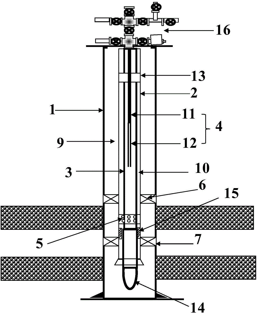
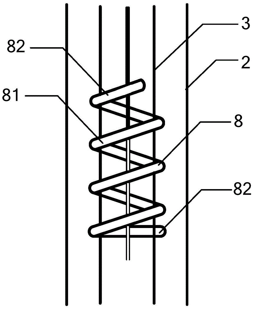
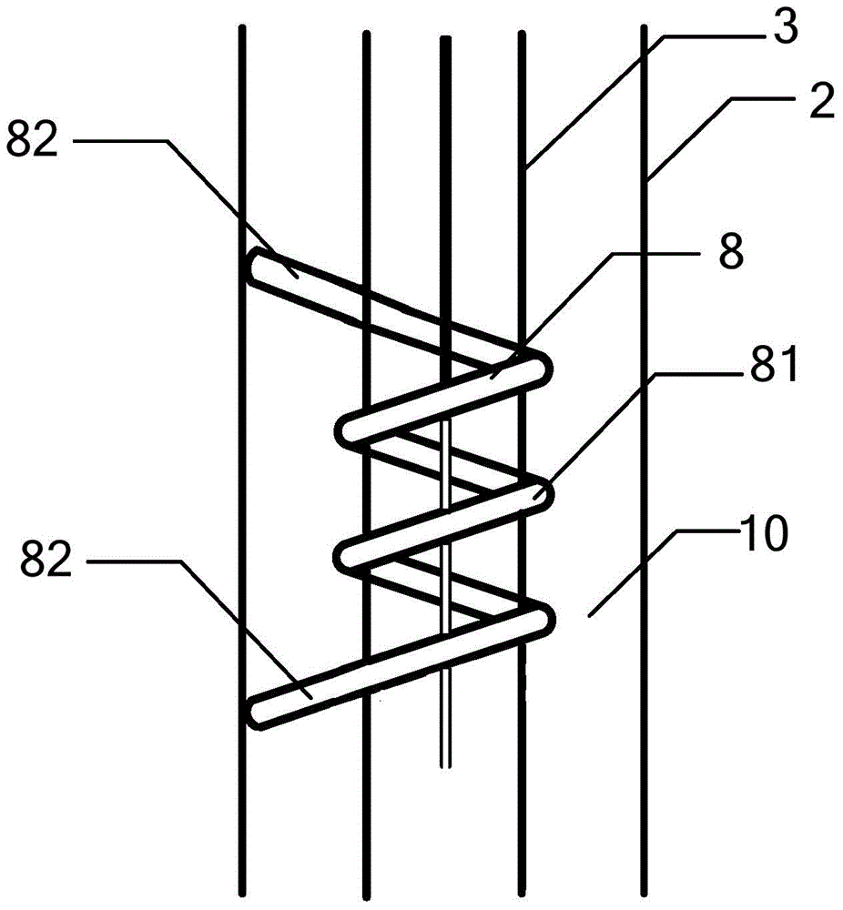
[0022] The embodiment of the present invention provides a layered ignition device for burning oil layers, such as figure 1 and Figure 2A As shown, the above-mentioned combustion oil layer layered ignition device mainly includes: casing 1, heat insulation p...


PUM


Abstract

The invention discloses a layered ignition device for in-situ combustion. According to the layered ignition device for the in-situ combustion, an electric ignition device is arranged in a cavity of a Pupping oil pipe, an insulated pipe sleeves the Pupping oil pipe, and a casing sleeves the insulated pipe; the electric ignition device comprises an electric igniter cable and an electric igniter heating section, and the electric igniter cable is connected with a power supply; a first annular space forms between the casing and the insulated pipe; a second annular space forms between the insulated pipe and the Pupping oil pipe; a first packer and a second packer are arranged in the first annular space at intervals, and an upper gas filling space remains between the first packer and the second packer; an upper gas distribution device located in the upper gas filling space is arranged on the insulated pipe; a reinforced heat transfer device comprises a winding section and two contact sections; when the temperature of the Pupping oil pipe is lower than a preset value, the reinforced heat transfer device integrally winds the Pupping oil pipe, and when the temperature of the Pupping oil pipe is larger than or equal to the other preset value, the contact sections are supported to contact with the insulated pipe.

Description

technical field [0001] The present invention relates to a combustion oil layer ignition technology, in particular, relates to a combustion oil layer layered ignition device. Background technique [0002] At present, the ignition technologies commonly used in heavy oil reservoirs mainly include steam injection spontaneous ignition, steam injection + chemical agent combustion-assisted ignition, and mobile electric ignition. However, some blocks in the fire-burning oil layer are multi-layer fires, and layered ignition and gas injection are required. Due to the limited space of the pipe string for layered injection, it is impossible to implement layered ignition with a mobile electric igniter. Therefore, the layered ignition on site The main methods are steam injection spontaneous ignition and steam injection + chemical agent combustion-assisted ignition. However, these two ignition methods have the following problems: the success rate of ignition is not high. Because the rema...

Claims


Application Information

Patent Timeline
IPC IPC(8): E21B43/243
CPCE21B43/243
Inventor 于晓聪阚长宾杨宝春龙华郝瑞辉刘锦马薇赵树杰汪小平杨显志孙鹿恒陈东明黄小雷刘江玲闫绪鹏吕政关泽寰
Owner PETROCHINA CO LTD
Why Eureka
Try Eureka