
Chain blocker and chain tensioner

A chain and accommodating technology, applied in the direction of earthwork drilling, slitting machinery, etc., can solve the problems of increasing failure points, increasing the cost of main engine, wasting manpower, etc., to reduce additional tensioning devices, reduce design failure points, and improve labor efficiency. productivity effect

Active Publication Date: 2017-06-06
SANY HEAVY EQUIP
View PDF5 Cites 0 Cited by
  • Summary
  • Abstract
  • Description
  • Claims
  • Application Information

AI Technical Summary

Problems solved by technology

At the same time, many people on site are required to control. After the control is completed, the linking operation will not only increase the cost of the main engine, bring inconvenience to the design, increase failure points, but also waste manpower and material resources, increase the linking operation time and operation difficulty.
[0003] It can be seen that the chain tensioning method applied to the two-speed motor dragging method, whether it is tensioning by using a hydraulic motor or using a brake disc, the chain connection and chain tightening process is too cumbersome and complicated, and the operation is difficult and wasteful. Manpower and material resources

Method used


Image

  • Chain blocker and chain tensioner
  • Chain blocker and chain tensioner
  • Chain blocker and chain tensioner

Examples


Embodiment Construction

[0043] The following will clearly and completely describe the technical solutions in the embodiments of the present invention with reference to the accompanying drawings in the embodiments of the present invention. Obviously, the described embodiments are only some, not all, embodiments of the present invention. Based on the embodiments of the present invention, all other embodiments obtained by persons of ordinary skill in the art without creative efforts fall within the protection scope of the present invention.

[0044] It should be noted that, in the case of no conflict, the embodiments of the present invention and the features in the embodiments can be combined with each other.

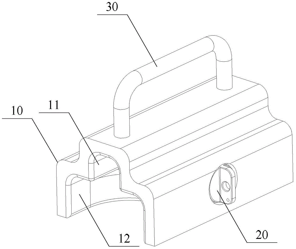
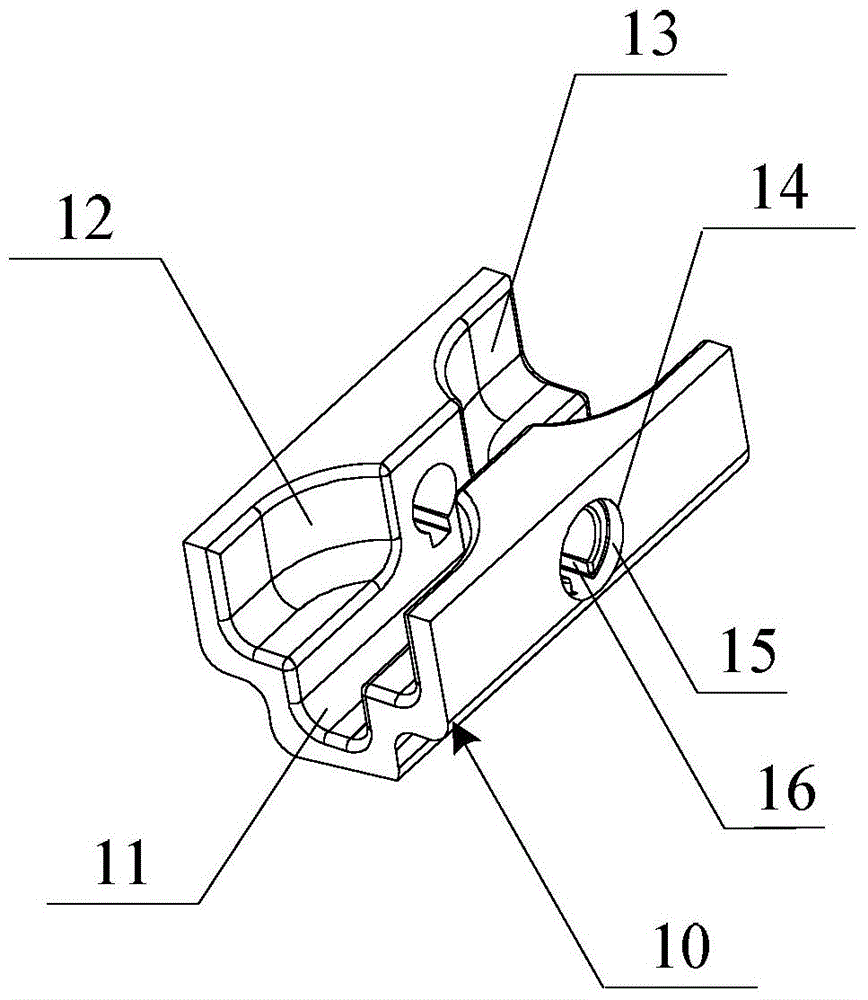
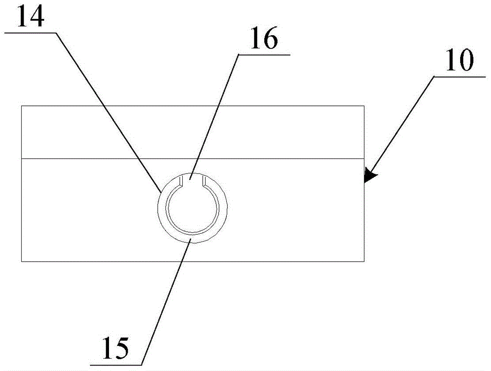
[0045] refer to Figures 1 to 7 , which shows the chain blocker proposed by the embodiment of the present invention. Below in conjunction with accompanying drawing, each embodiment of the present invention is described further:

[0046] Chain blocker embodiment

[0047] Such as figure 1 and...


PUM


Abstract

The invention discloses a chain stopper and a chain tightening device. The chain stopper comprises: a chain accommodation groove, the groove wall is symmetrically opened with installation holes left and right; the chain accommodation groove is used for accommodating a transmission chain; a safety bolt , plugged into the installation hole, used to fasten the transmission chain. The chain tightening device includes at least two chain stoppers of any of the above types, which are used to tighten and fix the round-link chain driven by the variable frequency motor; one of the chain stoppers is set at one end of any carriage of the round-link chain, and the other The chain blocker is arranged at the other end of the slide frame. Therefore, adopting the technical solution of the present invention can improve labor productivity, reduce the cost of the host machine, and get rid of the space limitation.

Description

technical field [0001] The invention relates to the field of engineering machinery, in particular to a chain stopper and a chain tightening device. Background technique [0002] With the development of coal plow and frequency conversion control technology, the traditional two-speed motor driving mode of coal plow has been gradually replaced by frequency conversion motor driving mode. In the tensioning process of the coal plow chain, not only additional tensioning devices, such as hydraulic motor chain tensioning devices, are required, but also corresponding interfaces and transmission parts, such as gears, need to be designed for the transmission part of the coal plow. At the same time, many people on site are required to control. After the control is completed, the linking operation will not only increase the cost of the main engine, bring inconvenience to the design, increase failure points, but also waste manpower and material resources, increase the linking operation tim...

Claims


Application Information

Patent Timeline
Patent Type & Authority Patents(China)
IPC IPC(8): E21C35/00E21C27/34
CPCE21C27/34E21C35/00
Inventor 张树齐杜鹏
Owner SANY HEAVY EQUIP
Learn More