Slurry pump sump

A slurry pump and pump pool technology, applied in the direction of pumps, non-displacement pumps, non-variable capacity pumps, etc., can solve the problem that the vicious cycle cannot be eliminated in a short time, and achieve the effect of promoting promotion.

Inactive Publication Date: 2015-04-01
攀枝花钢城集团瑞矿工业有限公司
View PDF4 Cites 2 Cited by
  • Summary
  • Abstract
  • Description
  • Claims
  • Application Information

AI Technical Summary

Problems solved by technology

When the ore collection reaches a certain height, the phenomenon of "collapse" causes the minerals entering the inlet area of ​​the slurry pump to increase instantaneously, exceeding the rated conveying concentration of the equipment, which further promotes the ore collection away from the slurry pump side and forms a vicious circle. This vicious circle cannot be eliminated in a short time

Method used


Image

  • Slurry pump sump

Examples


Embodiment Construction

[0013] The present invention will be further described below in conjunction with the accompanying drawings.

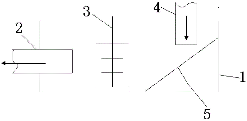
[0014] Such as figure 1 The pump pool of the slurry pump shown includes a pump pool 1, a slurry pump 2 is provided on one side of the pump pool 1, and an anti-stacking device is provided on the side opposite to the slurry pump 2 in the pump pool 1 5. A feed port 4 is provided above the anti-stacking device 5 .

[0015] The focus of the design of the present invention is to solve the problem of "slag slurry ore collection". Therefore, an anti-stockpiling device 5 is added at first, and the anti-stockpiling device 5 can guide the slurry input from the feed port 4 to the slurry pump 2 in time, fundamentally completely preventing the possibility of ore collection. Of course, the preferred and simplest structure of the anti-stocking device 5 here is exactly the material guide swash plate, such as figure 1 As shown, the sloping plate guides the slurry to flow to the slurr...


PUM


Abstract

The invention relates to the field of mineral processing equipment, in particular to a slurry pump sump. The slurry pump sump aims to solve the technical problems, and can effectively prevent slurry from collecting nodules, so that the concentration of the slurry keeps stable during delivery of the slurry. According to the technical scheme for solving the technical problems, the slurry pump sump comprises a pump sump; one side of the pump sump is provided with a slurry pump; one side in the pump sump opposite to a slurry pump is provided with an anti-stacking device; and a feeding inlet is formed in the upper part of the anti-stacking device. The slurry pump sump is ingenious in design, the improvement for the pump sump is effective and small, the slurry pump sump is suitable for promotion of the existing slurry pump, and also applied to production occasions requiring stable concentration of the slurry during delivery.

Description

technical field [0001] The invention relates to the field of mineral processing equipment, in particular to a slurry pump pool. Background technique [0002] At present, the pump pool is an indispensable container for collecting materials in the process of conveying materials by the slurry pump. At present, due to the impression of the production process itself, the concentration and amount of minerals entering the pump pool from the previous process are unstable, and the bottom of the pump pool is a cuboid, so it is easy to form ore collection on the side away from the slurry pump. When the ore collection reaches a certain height, the phenomenon of "collapse" causes the minerals entering the inlet area of ​​the slurry pump to increase instantaneously, exceeding the rated conveying concentration of the equipment, which further promotes the ore collection away from the slurry pump side and forms a vicious circle. This vicious circle cannot be eliminated in a short time. Co...

Claims


Application Information

Patent Timeline
Patent Type & Authority Applications(China)
IPC IPC(8): F04D7/04B01D21/02B01F3/00B01F23/00
CPCB01D21/02F04D7/04B01F23/00
Inventor 李大平宋科曾林
Owner 攀枝花钢城集团瑞矿工业有限公司
Why Eureka
Try Eureka