Clutch and variable speed driving hub

A clutch and hub technology, applied in the fields of variable-speed drive hubs, motors, clutches, and transmission components, can solve the problems of clutch failure, harsh noise, etc., and achieve the effects of long service life, large compensation, and stable performance.

Active Publication Date: 2015-04-01
ZHEJIANG DINGLI TIANYI AUTO PARTS CO LTD
View PDF13 Cites 17 Cited by
  • Summary
  • Abstract
  • Description
  • Claims
  • Application Information

AI Technical Summary

Problems solved by technology

The variable speed drive hub with this structure can only shift gears below 14km / h. If the shift speed setting exceeds 14km / h, such as the market demand of 18km / h, the clutch cannot be engaged and harsh noises will be emitted.

Method used


Image

  • Clutch and variable speed driving hub
  • Clutch and variable speed driving hub
  • Clutch and variable speed driving hub

Examples


Embodiment 1

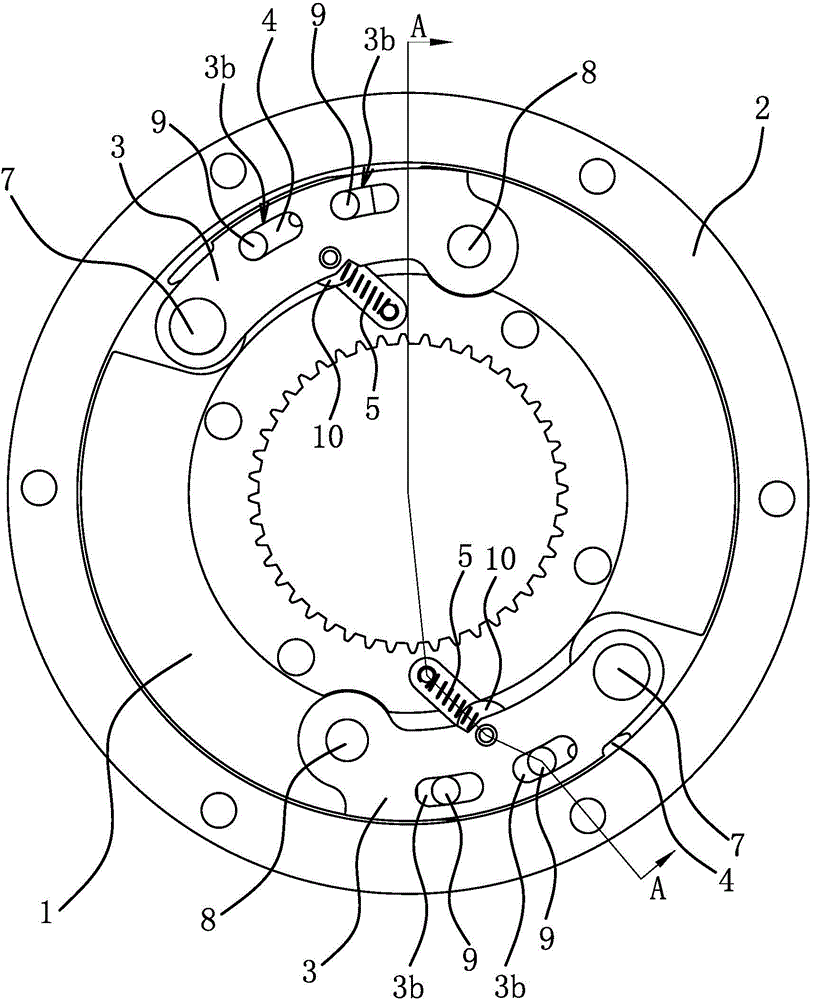
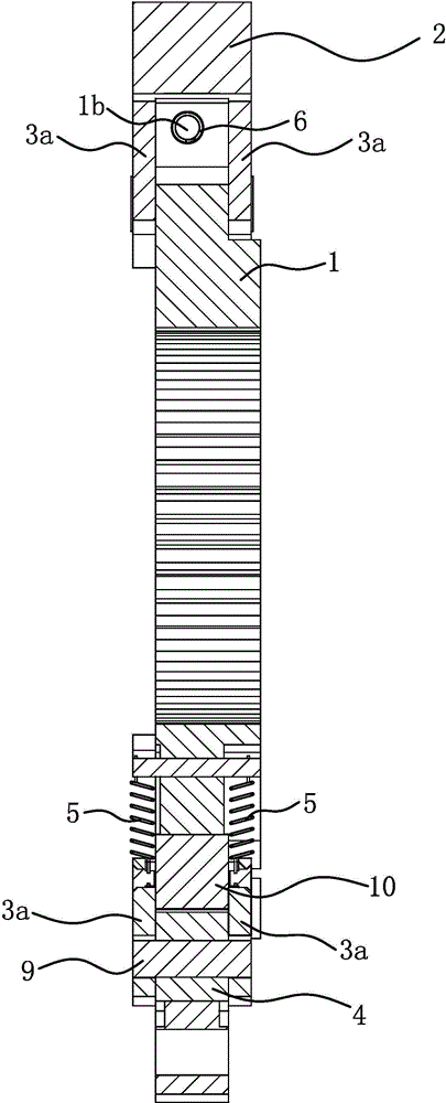
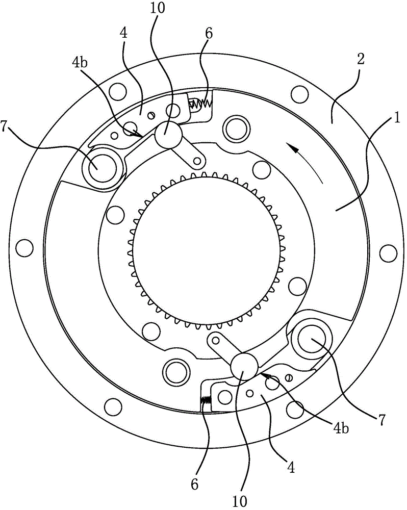
[0039] Such as Figure 1 to Figure 4 As shown, the clutch includes an inner connecting plate 1 , a friction ring 2 , a swing arm 3 , a friction block 4 , a first elastic member 5 and a second elastic member 6 .

[0040]The inner connecting plate 1 is circular, and the friction ring 2 is sleeved outside the inner connecting plate 1 , and the inner connecting plate 1 and the friction ring 2 are arranged coaxially. The number of swing arms 3 is at least two groups, and the swing arms 3 are evenly distributed along the circumference of the inner connecting plate 1; the number of swing arms 3 given in the drawings of this specification is two groups; . The other end of the swing arm 3 is fixedly connected with a first counterweight 7 . Specifically, each set of swing arms 3 includes two strip-shaped swing plates 3a, and the two swing plates 3a are respectively located on both sides of the inner connecting plate 1; a hinge shaft 8 is fixed on the inner connecting plate 1, and the ...

Embodiment 2

[0055] The structure and principle of this embodiment are basically the same as that of Embodiment 1, and the basic similarities will not be described redundantly. Only the differences will be described. The difference is that the other end of the swing arm 3 is not fixed with the first counterweight 7, the friction block 4 is connected to the other end of the swing arm 3 .

Embodiment 3

[0057] The structure and principle of this embodiment are basically the same as those of Embodiment 1, and the basic similarities will not be described in detail. Only the differences are described. The difference is that the first elastic member 5 is a torsion spring, and the torsion spring has a cylindrical shape. The winding part and two rod-shaped force parts, the cylindrical winding part is sleeved on the hinge shaft 8, one rod-shaped force part is connected with the inner connecting plate 1, and the other rod-shaped force part is connected with the swing arm 3.


PUM


Abstract

The invention provides a clutch and a variable speed driving hub, belongs to the technical field of engineering components, and solves the problem that the clutch in the existing variable speed driving hub can only be subjected to gear shifting below 14 km / h. The clutch comprises an inner connecting plate, a friction ring and at least two groups of swing arms, wherein a first elastic member, which can enable the centrifugally rotated swing arms to reset, is arranged between each group of the swing arms and the inner connecting plate; friction blocks, with the number same as that of the swing arms, are arranged between the inner connecting plate and the friction ring; the friction blocks and the swing arms are arranged in a one-to-one corresponding manner; the friction blocks are connected with the swing arms through a connection structure which can enable the friction blocks to circumferentially slide relative to the inner connecting plate; a second elastic member, which can enable the circumferentially slid friction blocks to reset, is arranged between each group of the friction blocks and the corresponding swing arms or between each group of the friction blocks and the inner connecting plate; a transmission mechanism, which can enable the friction blocks and the inner connecting plate to realize transmission after the friction blocks are in contact with the friction ring, is arranged between each group of the friction blocks and the inner connecting plate. According to the variable speed driving hub with the clutch provided by the invention, the flexible adjustment can be performed in accordance with the market requirements on gear shifting speed.

Description

technical field [0001] The invention belongs to the technical field of engineering components, and relates to a transmission component, in particular to a clutch. [0002] The invention belongs to the field of electrical technology, and relates to a motor, in particular to a variable-speed drive wheel hub. Background technique [0003] There are two main types of speed change devices used in driving the hub, one is electronic stepless controller speed change, and the other is mechanical speed change. Electronic stepless controller variable speed can obtain from 0 to the highest speed of the motor, and has a good speed change curve, but its output torque is directly consistent with the change of the input current of the motor; when the voltage is constant, the motor The greater the load, the greater the current required. Mechanical transmission is divided into stepped transmission and continuously variable transmission. Mechanical variable speed can obtain output torques o...

Claims


Application Information

Patent Timeline
Patent Type & Authority Applications(China)
IPC IPC(8): F16D43/04H02K7/108
Inventor 李跃岩
Owner ZHEJIANG DINGLI TIANYI AUTO PARTS CO LTD
Why Eureka
Try Eureka