Spectrum analysis method of FPGA (Field Programmable Gate Array) digital logic signal

A digital logic and spectrum analysis technology, applied in the field of high-speed signal spectrum, can solve the problems that digital logic signals cannot fully reflect signal characteristics, bandwidth, real-time sampling and data processing capabilities, high technical implementation difficulty and high cost

Active Publication Date: 2015-04-01
NANJING GUORUI ANTAIXIN TECH
View PDF4 Cites 3 Cited by
  • Summary
  • Abstract
  • Description
  • Claims
  • Application Information

AI Technical Summary

Problems solved by technology

[0002] In high-speed digital systems, there are many ways and means of simulation software and logic analyzers to verify whether the digital logic function and timing are correct, but whether it is the simulation software used for function and timing simulation or the logic analyzer for actual measurement The analysis is done in the time domain. However, when the high-speed digital signal is output, it is often aperiodic due to the reflection, interference or ground potential jump caused by the mismatch or unconnected terminal transmission line, and the burr and oscillation caused by the bus competition; The edge signals of edge signals also often contain important harmonic information above their fundamental frequency. Therefore, for traditional time-domain test instruments, the requirements for bandwidth, real-time sampling and data processing capabilities are relatively high, and the technical implementation is difficult and costly. In addition, the analysis of digital logic signals from the time domain cannot fully reflect the characteristics of the signals

Method used


Image

  • Spectrum analysis method of FPGA (Field Programmable Gate Array) digital logic signal
  • Spectrum analysis method of FPGA (Field Programmable Gate Array) digital logic signal
  • Spectrum analysis method of FPGA (Field Programmable Gate Array) digital logic signal

Examples


Embodiment Construction

[0022] The spectrum analysis method of the FPGA digital logic signal provided by the present invention will be described in detail below in conjunction with the accompanying drawings, but this does not constitute a limitation to the present invention.

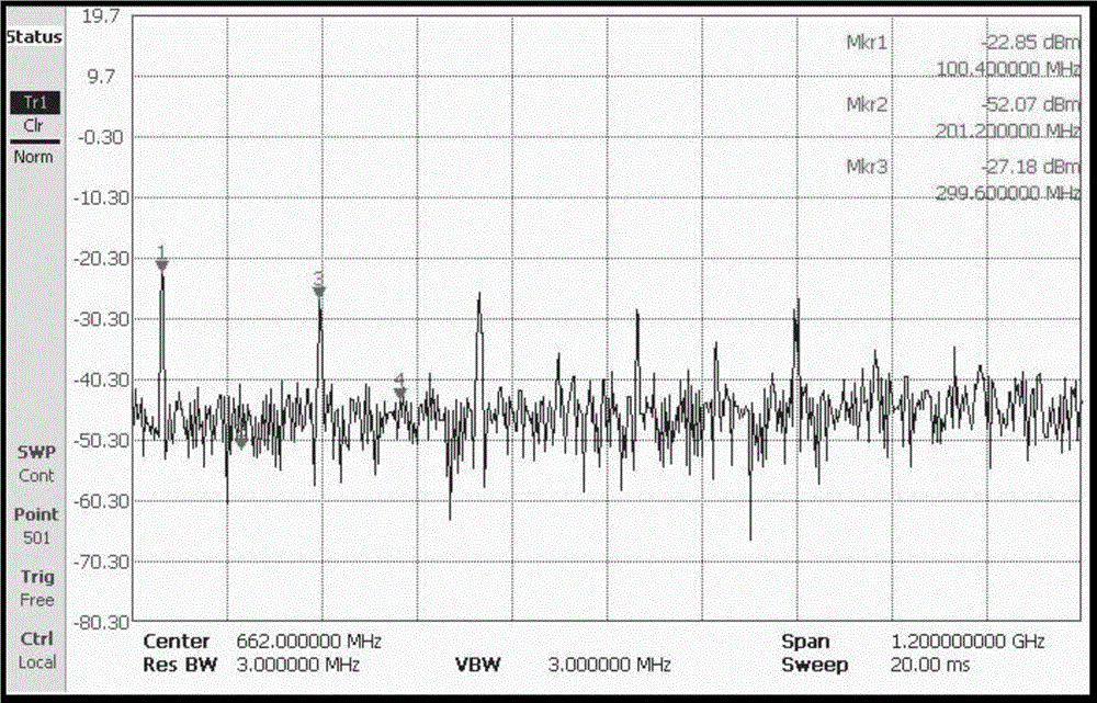
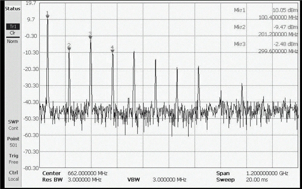
[0023] Through computer simulation and hardware system experiment, it is determined that the harmonics of periodic clock digital logic signal spectrum analysis in the process of high-speed digital logic signal spectrum analysis should be above 8 times. Clock digital frequency spectrum is theoretically infinite, but in engineering applications, only limited harmonics can be used for analysis, so in practice, appropriate harmonics should be used for compromise.

[0024] according to figure 1 The overall plan is divided into two steps to analyze the target system. The first step is to output the frequency spectrum of the clock signal through computer simulation, and the digital logic signal L outputted by the digital logic functio...


PUM


Abstract

The invention relates to a spectrum analysis method of an FPGA (Field Programmable Gate Array) digital logic signal. The method comprises the following steps of implementing computer logic simulation on a logic function which occurs during the process of realizing an original digital logic signal Ls; converting the digital logic signal LS of computer logic simulation output to a digital signal Fs available for spectral analysis; implementing discrete Fourier transformation on the Fs to obtain a spectrum Ms(e<jw>) of the digital signal; actually outputting the logic function which occurs during the whole realization process of the digital logic signal Ls, and implementing actual spectral measurement on the FPGA digital logic function through a spectrum analyzer to obtain a spectrum Mr(e<jw>) of an actual output digital signal Fr; comparatively analyzing the Fs spectrum Ms(e<jw>) and the Fr spectrum Mr(e<jw>). According to the method, the analysis method of the digital logic signal is expanded from time domain to frequency domain; compared with a traditional analysis method of the digital logic signal, the method has the advantage of judging whether the digital logic signal quality, the digital logic function and the time sequence are correct or not by using a method of combining the frequency domain simulation of the digital logic signal and the spectrum analysis of the actual signal.

Description

technical field [0001] The invention belongs to the technical field of high-speed signal spectrum, and more specifically, relates to a spectrum analysis technology of high-speed digital logic signal. Background technique [0002] In high-speed digital systems, there are many ways and means of simulation software and logic analyzers to verify whether the digital logic function and timing are correct, but whether it is the simulation software used for function and timing simulation or the logic analyzer for actual measurement The analysis is done in the time domain. However, when the high-speed digital signal is output, it is often aperiodic due to the reflection, interference or ground potential jump caused by the mismatch or unconnected terminal transmission line, and the burr and oscillation caused by the bus competition; The edge signals of edge signals also often contain important harmonic information above their fundamental frequency. Therefore, for traditional time-doma...

Claims


Application Information

Patent Timeline
Patent Type & Authority Applications(China)
IPC IPC(8): G01R23/16
Inventor 钟景华李为
Owner NANJING GUORUI ANTAIXIN TECH
Why Eureka
Try Eureka