

Air pressure ejector device
A catapult and air pressure technology, applied in the direction of overhead lines/cable equipment, etc., can solve the problems of low launch efficiency and compressed air utilization, launch distance end, low work efficiency, etc., to improve launch efficiency and compressed air utilization , increase the contact area, the effect of low manufacturing cost
- Summary
- Abstract
- Description
- Claims
- Application Information
AI Technical Summary
Problems solved by technology
Method used
Image

Examples
Embodiment Construction
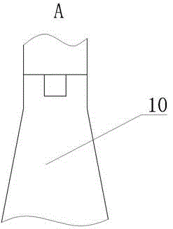
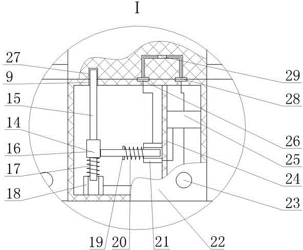
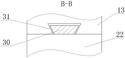
[0009] Pneumatic catapult devices such as figure 1 , figure 2 As shown, the launch tube 2 is included, the launch tube 2 is a cylindrical tube with a sealed upper opening at the bottom, a compressed air bottle 3, a one-way valve 4, an air storage chamber 5 and a sandbag 7 are arranged in the launch tube 2, and the compressed air bottle 3 is located at the launcher. The bottom of the cylinder 2, the upper part of the compressed air bottle 3 is connected to the one-way valve 4, the upper part of the one-way valve 4 is connected to the air storage chamber 5, the compressed air bottle 3 sends high-pressure air to the air storage chamber 5 through the one-way valve 4, and the air storage chamber 5 An electromagnetic valve 11 is arranged on the upper part of the cylinder, and the electromagnetic valve 11 controls the delivery of gas in the gas storage chamber 5 to the outside world. The ejector 6 is arranged on the upper part of the electromagnetic valve 11 in the launching tube 2....
PUM
 Abstract
Description
Claims
Application Information