Tool for demounting brake pads of lathe

A brake pad and tool technology, applied in the field of brake pad removal tools, can solve the problems of low disassembly efficiency, time-consuming and labor-intensive problems

Pending Publication Date: 2015-04-08
CHONGQING YUANCHUANG AUTOMATION EQUIP
View PDF13 Cites 0 Cited by
  • Summary
  • Abstract
  • Description
  • Claims
  • Application Information

AI Technical Summary

Problems solved by technology

[0004] The technical problem to be solved by the present invention is to provide a tool for dismantling the br

Method used


Image

  • Tool for demounting brake pads of lathe
  • Tool for demounting brake pads of lathe
  • Tool for demounting brake pads of lathe

Examples


Embodiment Construction

[0015] The present invention will be described in further detail below by means of specific embodiments:

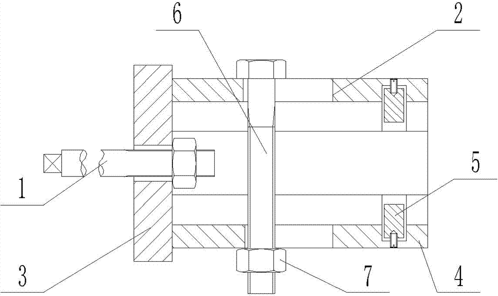
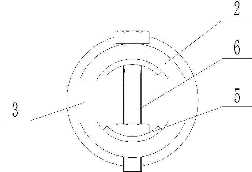
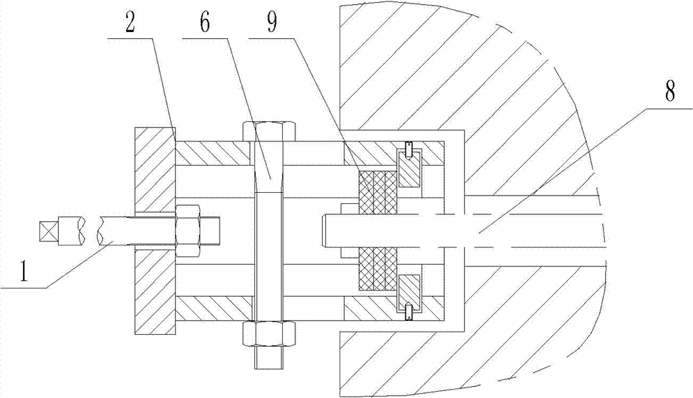
[0016] The reference signs in the drawings of the description include: pull rod 1 , clamping device 2 , pull plate 3 , clamp plate 4 , clamp block 5 , bolt 6 , lock nut 7 , spline shaft 8 , and brake pad 9 .

[0017] The embodiment is basically as attached figure 1 , figure 2 , image 3 Shown: the tool used to disassemble the brake pad 9 of the lathe, including a pull rod 1 and a clamping device 2, the pull rod 1 is threaded with the clamping device 2; the clamping device 2 includes a pull plate 3 and two clamping plates 4, the pull plate 3 welded with the clamping plate 4, the cross-sectional shape of the clamping plate 4 is arc-shaped, and the clamping plate 4 is provided with a strip-shaped through hole and an arc-shaped groove, and a clamping block 5 is arranged in the arc-shaped groove, and the clamping block 5 It is connected with the clamping plate 4 by a set s...


PUM


Abstract

The invention discloses a tool for demounting brake pads of lathes. The tool comprises a pull rod and a clamping device which are in detachable connection. The clamping device comprises a pull plate and two clamping plates which are fixedly connected. The sections of the clamping plates are arc, and strip-shaped through holes and arc grooves are formed in the clamping plate. Clamping blocks are arranged in the arc grooves and are detachably connected with the clamping plates. A bolt is arranged between the clamping plates, the diameter of a threaded rod of the bolt is smaller than the width of the strip-shaped through holes in the clamping plates, and a locking nut is arranged on the bolt. A through hole is formed in the pull plate, the aperture of the through hole is larger than the diameter of the pull rod, and a nut is arranged in the through hole. The pull plate is composed of a clamping part, a polished rod part and a threaded part from left to right in sequence, and threads of the thread part of the pull plate are matched with the nut on the pull plate. The tool for demounting brake pads of lathes overcomes defects of the prior art of low demounting efficiency and time and energy waste during demounting of the brake pads on the lathes.

Description

technical field [0001] The invention relates to the field of brake pad removal tools, in particular to a tool for removing brake pads of a lathe. Background technique [0002] Brake pads are generally composed of steel plates, adhesive insulation layers and friction blocks. The steel plates must be painted to prevent rust. During the painting process, SMT-4 furnace temperature tracker is used to detect the temperature distribution during the painting process to ensure the quality. The heat insulation layer is composed of materials that do not conduct heat, and the purpose is heat insulation. The friction block is composed of friction material and adhesive, which is squeezed on the brake disc or brake drum to generate friction during braking, so as to achieve the purpose of deceleration and braking. Due to friction, the friction block will be gradually worn, generally speaking, the lower the cost of the brake pads, the faster the wear. [0003] The frequent start and stop o...

Claims


Application Information

Patent Timeline
IPC IPC(8): B25B27/00
CPCB25B27/00
Inventor 陈振丰
Owner CHONGQING YUANCHUANG AUTOMATION EQUIP
Why Eureka
Try Eureka