Supercharge Your Innovation With Domain-Expert AI Agents!

Vibration wheel for vibratory roller

A vibratory roller and vibrating wheel technology, applied in the field of vibrating wheels, can solve the problems of excessive lubricating oil service temperature, slow air convection, limited heat transfer, etc., to achieve good working characteristics and prolong working life.

Inactive Publication Date: 2015-04-08
柳工无锡路面机械有限公司
View PDF7 Cites 0 Cited by
  • Summary
  • Abstract
  • Description
  • Claims
  • Application Information

AI Technical Summary

Problems solved by technology

[0003] The biggest defect of this structure is that the air convection between the inner ring and the outer ring is too slow, the heat transfer is limited, and the contact area between the web and the lubricating oil is too small, and the heat dissipation capacity is insufficient
This will easily lead to a higher temperature of the lubricating oil, resulting in a temperature exceeding the reasonable range of the lubricating oil, causing early failure of the lubricating oil, and reducing the life of the vibration bearing and premature damage

Method used


Image

  • Vibration wheel for vibratory roller
  • Vibration wheel for vibratory roller

Examples


Embodiment Construction

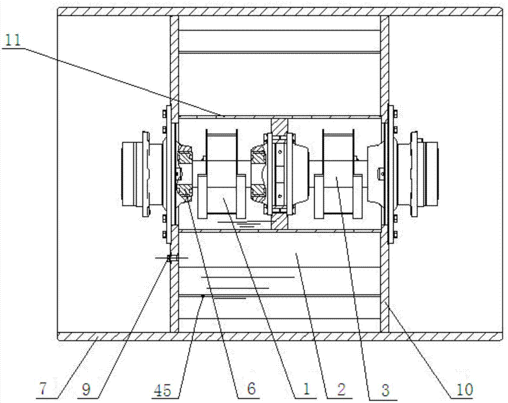
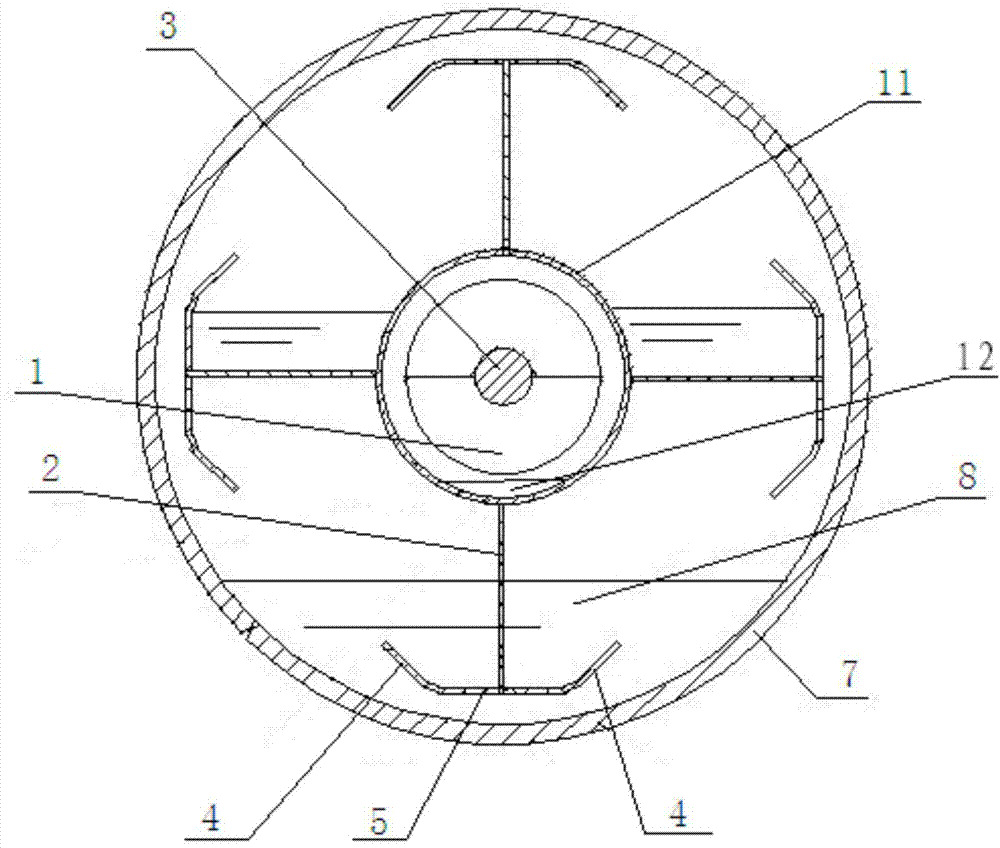
[0013] figure 1 , figure 2 As shown, it relates to a vibrating wheel for a vibratory roller, including an outer ring 7, a web 10 arranged inside the outer ring 7, and an inner ring 11 arranged in the middle of the web 10; the inner ring 11 is provided with a vibration shaft 3 with an eccentric shaft 1, and the two ends of the vibration shaft 3 are fixedly connected to the web 10 through a vibration bearing 6; between the outer ring 7, the inner ring 11 and the web 10 is formed Sealed oil storage chamber 8. Wherein, a plurality of ribs 2 extending into the oil storage cavity 8 are evenly distributed on the outer edge of the inner ring 11 , and a supporting plate 45 is provided at the lower end of the ribs 2 . Wherein, when the bottom end of the supporting plate 45 is between 5-10 cm from the inner wall of the outer ring 5, the supporting plate 45 can better displace the oil in the oil storage chamber 8 when the vibrating wheel is working. The coolant is brought into the vib...


PUM


Abstract

The invention discloses a vibration wheel for a vibratory roller. The vibration wheel comprises an outer ring, a center plate arranged inside the outer ring and an inner ring arranged in the middle of the center plate. A vibration shaft with an eccentric shaft is arranged in the inner ring, and the two ends of the vibration shaft are fixedly connected with the center plate through vibration bearings. A sealed oil storage cavity is formed among the outer ring, the inner ring and the centre plate. A plurality of rib plates extending to the oil storage cavity are evenly distributed on the outer edge of the inner ring, and a supporting plate is arranged at the lower ends of the rib plates. According to the vibration wheel, lubricating oil can be kept within the best temperature range all the time, it is ensured that the lubricating oil is in the good working characteristics, and the service life of the vibration wheel is prolonged.

Description

technical field [0001] The invention relates to a vibration wheel for a vibratory road roller, belonging to the technical field of vibratory road rollers. Background technique [0002] The vibrating wheel of a traditional vibratory roller consists of an eccentric shaft, lubricating oil, inner ring, rib plate, left and right supporting plates, outer ring, coolant, web, vibration bearing and plug. When the eccentric shaft rotates, the centrifugal force will drive the entire steel wheel to vibrate. At the same time, the centrifugal force will generate a lot of heat when the vibration bearing rotates. Since the vibration wheel rolls, the web can bring lubricating oil into the vibration bearing to lubricate the vibration bearing. And the lubricating oil takes away the heat on the vibrating bearing and transmits it to the inner ring and the web while lubricating. [0003] The biggest defect of this structure is that the air convection between the inner ring and the outer ring is ...

Claims


Application Information

Patent Timeline
Patent Type & Authority Applications(China)
IPC IPC(8): E01C19/28
CPCE01C19/286
Inventor 徐益道钟玉林
Owner 柳工无锡路面机械有限公司
Features
  • R&D
  • Intellectual Property
  • Life Sciences
  • Materials
  • Tech Scout
  • Unparalleled Data Quality
  • Higher Quality Content
  • 60% Fewer Hallucinations
Learn More