
Elevator motor structure

A technology of motor structure and lifter, which is applied in the direction of manual mechanism, power control mechanism, wing leaf control mechanism, etc., which can solve the problems of easy misalignment, affecting the effect, and large axial force of the worm, so as to prevent axial deviation. Move, improve the service life, improve the effect of self-locking strength

Active Publication Date: 2015-04-08
宁波世通汽车零部件有限公司
View PDF6 Cites 3 Cited by
  • Summary
  • Abstract
  • Description
  • Claims
  • Application Information

AI Technical Summary

Problems solved by technology

[0005] During the actual test, it was found that the inner and outer rings of the bearing are prone to misalignment due to the large axial force of the worm, which seriously affects its effect
In addition, the axial force of the worm also causes a certain deviation in the position of the rotor of the motor, which is also harmful to the motor itself.

Method used


Image

  • Elevator motor structure
  • Elevator motor structure
  • Elevator motor structure

Examples


Embodiment Construction

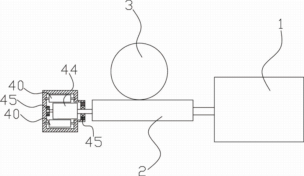
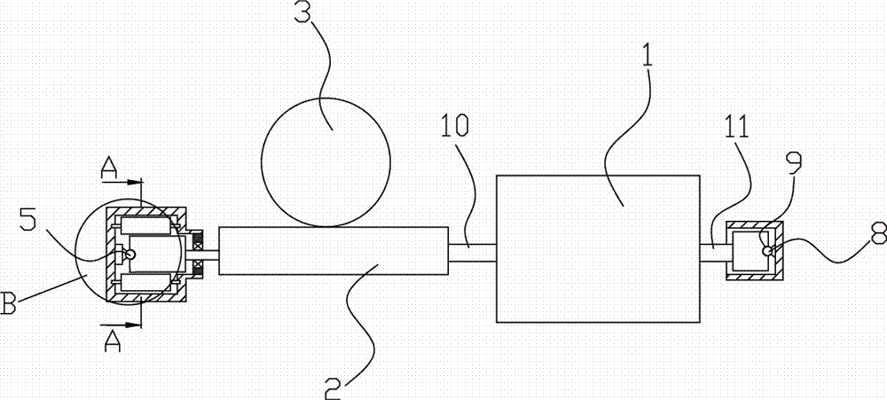
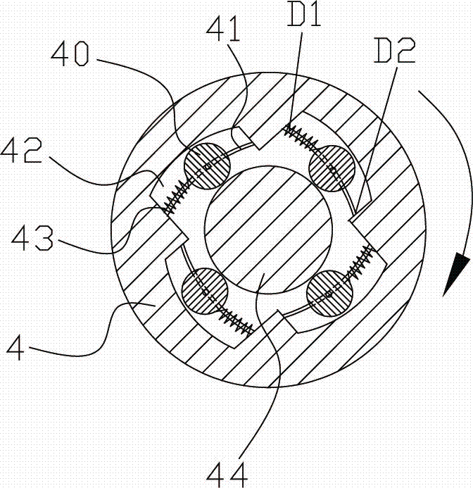
[0014] The present invention will be described in further detail below in conjunction with accompanying drawing and specific embodiment: see Figure 1 to Figure 2 , the elevator motor structure, including a motor 1, the two ends of the motor 1 are respectively drawn with a first output shaft 10 and a second output shaft 11, the first output shaft 10 is connected with a worm 2, and also includes a 2 meshed turbine 3, a rotating roller 44 is provided at one end of the worm 2, and a sleeve 4 is also included, and the rotating roller 44 is located in the sleeve 4, and at least one set of The extruding element 40, the extruding element 40 abuts against the rotating roller 44, a groove 42 for accommodating the extruding element 40 is arranged on the sleeve 4, and a sliding rail 41 is arranged in the groove 42, The extruding element 40 is slidably arranged on the slide rail 41 , and the elastic member 43 is arranged on the slide rail 41 against the extruding element 40 , and the slid...


PUM


Abstract

The invention discloses an elevator motor structure. The elevator motor structure comprises a motor, a worm, a turbine and a sleeve, wherein the turbine is meshed with the worm; a rotary roller is arranged at one end of the worm and is positioned in the sleeve; an extrusion element is arranged in the sleeve and propped against the rotary roller; a groove for accommodating the extrusion element is formed in the sleeve; a sliding rail is arranged in the groove; the extrusion element is slidably arranged on the sliding rail; an elastic piece propped against the extrusion element is arranged on the sliding rail; a first ball is arranged on the inner wall of the sleeve; a first ball seat matched with the first ball is arranged on one side of the rotary roller; a second roller is arranged on one side of a second output shaft; a second ball seat matched with the second ball is arranged on one side of the second output shaft. By the first ball and the second ball which are axially arranged on the worm, the worm can be fixed at the axial position, so that the axial offset of the worm is prevented, and the service life is greatly prolonged.

Description

technical field [0001] The invention relates to the field of motors, and more specifically, to a motor used on a car lifter. Background technique [0002] The sheave-type automobile window lifter motor includes a motor body, the output shaft of which is connected to a worm, and the worm meshes with a worm gear, and the worm drives the worm gear to rotate so that the worm gear winds the cable to realize the lifting of the car window. [0003] Since the window is required to be able to be limited at any position of the window, the worm gear and the worm are required to have a large self-locking force. At this time, the entire worm lead angle and the number of worm heads must not be increased to improve its self-locking force. However, while increasing the lead angle of the entire worm and the number of worm heads, it will inevitably cause the transmission efficiency of the entire worm and worm system to be low. In addition, increasing the lead angle of the entire worm and the...

Claims


Application Information

Patent Timeline
Patent Type & Authority Applications(China)
IPC IPC(8): E05F11/38E05F15/697H02K7/116
Inventor 陈世奇
Owner 宁波世通汽车零部件有限公司
Learn More