Measuring method for water-containing coal and rock down drill hole gas pressure observation system

A gas pressure and observation system technology, which is applied in the directions of surveying, earthwork drilling, wellbore/well components, etc., can solve problems such as water accumulation in downhole drilling, and achieve continuous and accurate measurement and reduce the effect of impact.

Inactive Publication Date: 2015-04-08
SHANDONG UNIV OF SCI & TECH
View PDF5 Cites 8 Cited by
  • Summary
  • Abstract
  • Description
  • Claims
  • Application Information

AI Technical Summary

Problems solved by technology

[0003] However, when the formation structure and roadway layout do not allow the construction of horizontal drilling and upward drilling, it is necessary to use downward drilling, and the traditional method cannot effectively solve the problem of water accumulation in the downward drilling

Method used


Image

  • Measuring method for water-containing coal and rock down drill hole gas pressure observation system
  • Measuring method for water-containing coal and rock down drill hole gas pressure observation system
  • Measuring method for water-containing coal and rock down drill hole gas pressure observation system

Examples


Embodiment 1

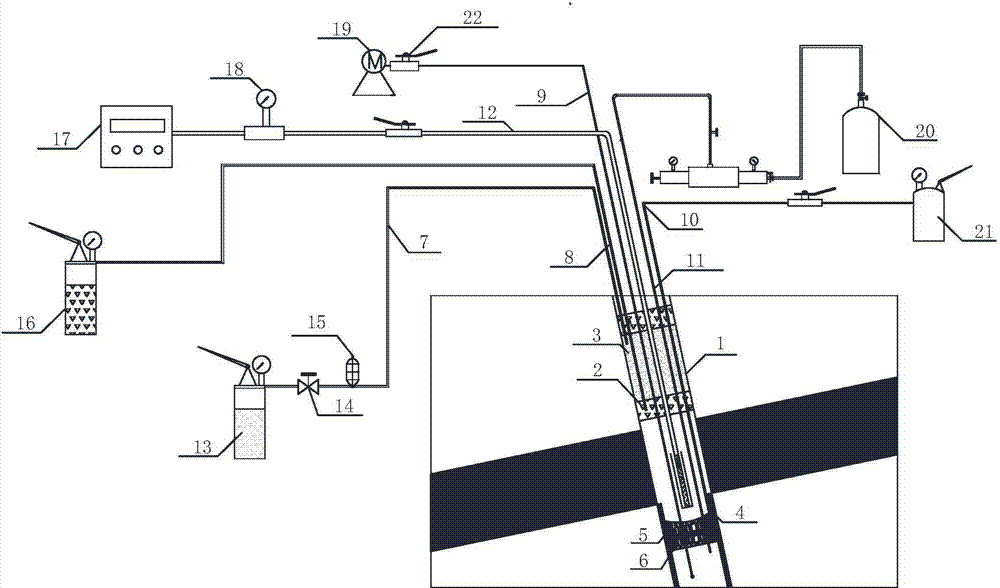
[0040] In the present invention, the method for measuring gas pressure observation system for downhole drilling in water-bearing coal and rock specifically includes the following steps:

[0041] (1) Drilling holes: Use conventional coal mine drilling equipment to drill down drill holes 1 in the coal rock roadway toward the coal seam, the hole deep to a certain distance through the coal seam;

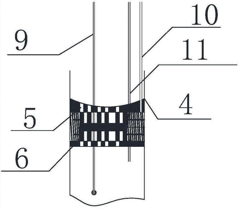
[0042] (2) Water-permeable device: clean up the debris in the borehole, install the water-permeable device 4 in the borehole, use the filling material to fill the pores between the water-permeable device 4 and the borehole 1, and do a pressure test after curing for a certain period of time , If the experiment is unsuccessful, reinstall the permeable device 4;

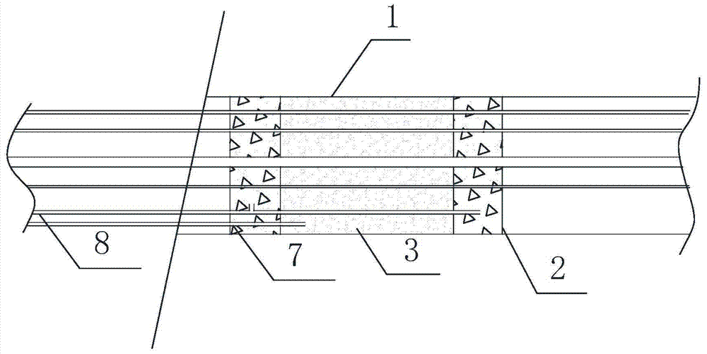
[0043] (3) Closed borehole: After the pressure test is successful, install the relevant pipes on the baffle, and use the baffle to form 2 No. 1 sealed chambers 2 and 1 No. 2 sealed chamber 3. First, use the curing material pressure tank ...

Embodiment 2

[0048] The difference from Example 1 is that the drilling drainage method in step (5) is different. The other drainage method is drainage under pressure difference conditions, that is, first use the air supply pipe 11 to perform a little pressure relief to form the upper and lower cavities. The pressure difference is then used for water permeation. After the water permeation is completed, the pressure of the oil pipeline 10 is released, the piston 6 moves under the pressure of the spring, and the permeable hole is closed by the piston, so that the permeable device 4 is in a sealed state; if the water volume is small, then The water is sealed under the permeable device 4, if the amount of water is large, the high-pressure gas tank 20 is used to press in the high-pressure gas through the air pipe 11, and the water can be discharged through the drainage pipe 9 or the water can be pumped out through the drainage motor 19.


PUM


Abstract

The invention provides a measuring method for a water-containing coal and rock down drill hole gas pressure observation system, and belongs to the technical field of mine gas pressure measurement. The measuring method concretely solves the problem that the gas pressure cannot be measured in a down drill hole due to water accumulation. The measuring method comprises the following steps that: firstly, a drill hole is drilled; then, experiment hardware is prepared, and the experiment hardware comprises a water permeable device, a sealing and blocking device and a pressure measuring device; next, the water permeable device is arranged in the drill hole, the gap between the water permeable device and the drill hole is filled by filling materials, and after the filling materials are cured, a pressure withstand test is performed for detection; then, the drill hole is sealed for secondary pressure withstand detection, and water in the drill hole is discharged out; and finally, the gas pressure measurement is performed through relevant auxiliary equipment. The measuring method has the advantages that the defect of influence on the gas pressure measurement caused by the water in the down drill hole can be better overcome, and the measuring method is particularly applicable to the gas pressure measurement in the water-containing coal and rock down drill hole.

Description

Technical field [0001] The invention belongs to the technical field of mine gas pressure measurement, and specifically relates to a measurement method of a water-bearing coal and rock gas pressure observation system. Background technique [0002] Gas pressure is an important parameter that marks the occurrence of coal seam gas. It is a key basic parameter when studying coal and gas outburst, gas emission, and gas drainage. Therefore, in order to study the law of coal seam gas occurrence and emission, it is necessary to measure coal seam gas pressure. According to the coal industry standard MT / T638-1996 "Method for Direct Measurement of Gas Pressure in Coal Seams in Coal Mines", the pressure test drill site should be selected in the roadway adjacent to the coal seam, and in general, it is usually selected to be level with the coal seam or lower than the coal seam The roadway is used as the location of the drill site, so that the boreholes constructed are all horizontal or upward ...

Claims


Application Information

Patent Timeline
Patent Type & Authority Applications(China)
IPC IPC(8): E21B47/06
CPCE21B47/06
Inventor 刘伟韬宋文成申建军张晓强张茂鹏谢祥祥刘士亮吕斌董文程宰慧赵春波刘超范龙邱磊
Owner SHANDONG UNIV OF SCI & TECH
Why Eureka
Try Eureka