Buffer spring plate

A buffer spring and buffer plate technology, applied in the direction of spring, spring/shock absorber, shock absorber, etc., can solve the problem of poor buffer effect, and achieve the effect of good buffer effect, simple structure, and easy promotion and use.

Inactive Publication Date: 2015-04-08
JIANGYIN SHENGYUAN COPPER MATERIAL
View PDF0 Cites 18 Cited by
  • Summary
  • Abstract
  • Description
  • Claims
  • Application Information

AI Technical Summary

Benefits of technology

This new design allows for better protection against shocks by providing three different levels of resistance with an intermediate layer that helps it work well over multiple periods without losing its ability or requiring more expensive maintenance than usual.

Problems solved by technology

The technical problem addressed in this patented technology relating to conventional springs that have limited ability for absorbing shocks without losing their function or being shorter than expected over time due to lacked space between certain parts within them.

Method used


Image

  • Buffer spring plate

Examples


Embodiment Construction

[0008] All features disclosed in this specification, or steps in all methods or processes disclosed, may be combined in any manner, except for mutually exclusive features and / or steps.

[0009] Any feature disclosed in this specification (including any appended claims, abstract and drawings), unless expressly stated otherwise, may be replaced by alternative features which are equivalent or serve a similar purpose. That is, unless expressly stated otherwise, each feature is one example only of a series of equivalent or similar features.

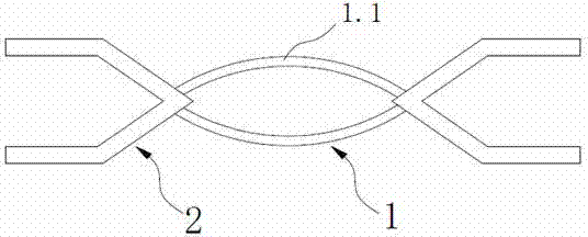
[0010] Such as figure 1 The buffer spring plate shown includes a middle plate 1, the two ends of the middle plate 1 are symmetrically provided with a buffer plate 2, the middle plate 1 includes a circular arc plate 1.1, and the two circular arc plates 1.1 are arranged opposite to each other , the buffer plate 2 is arranged in a V-shaped structure.

[0011] During use, the buffer plate 2 forms a primary buffer. After receiving a large impact ...


PUM


Abstract

The invention discloses a buffer spring plate. The buffer spring plate comprises a middle plate, wherein two ends of the middle plate are symmetrically provided with buffer plates, the middle plate comprises two arc-shaped plates, the two arc-shaped plates are oppositely arranged, and the buffer plates are of V-shaped structures. The buffer spring plate disclosed by the invention has the advantages that the structure is simple, the effect of carrying out two-stage buffering on an impact force through the buffer action of the buffer plates and the middle plate can be achieved, the buffer effect is good, the service life is long, the cost is reduced, and the promotion and the use are easy.

Description


Claims


Application Information

Patent Timeline
Owner JIANGYIN SHENGYUAN COPPER MATERIAL
Why Eureka
Try Eureka