
Control method for coriolis mass flow tube of variable sensor signal setting value

A sensor signal and control method technology, applied in the direction of direct mass flowmeter, mass flow measurement device, etc., can solve the problems of large fluctuation range of sensor signal amplitude, loss of digital drive system, large fluctuation, etc., and achieve the sensor output signal amplitude Stable, reduce signal volatility, adjust flexible and effective effects

Active Publication Date: 2015-04-08
HEFEI UNIV OF TECH
View PDF2 Cites 16 Cited by
  • Summary
  • Abstract
  • Description
  • Claims
  • Application Information

AI Technical Summary

Problems solved by technology

However, when measuring two-phase flow, the flow tube amplitude control method still adopts the control method of fixing the sensor signal setting value during single-phase flow measurement, and the sensor signal setting value is always fixed to the best amplitude of the sensor signal under single-phase flow , because there is always an error between the set value of the sensor signal and the amplitude of the sensor signal in the steady state, the integral factor of the PI controller of the integral limit is saturated and the output driving gain of the driving system is saturated, and the result is that the amplitude of the sensor signal varies with the flow tube The fluctuation range of the damping ratio is large, and the digital drive system loses the role of flow tube amplitude control
In order to make the flow tube obtain the best vibration under the two-phase flow, it is necessary to propose a flow tube amplitude control method that meets the two-phase flow, so as to solve the problem that the output signal of the sensor is not stable and fluctuates greatly

Method used


Image

  • Control method for coriolis mass flow tube of variable sensor signal setting value
  • Control method for coriolis mass flow tube of variable sensor signal setting value
  • Control method for coriolis mass flow tube of variable sensor signal setting value

Examples


Embodiment Construction

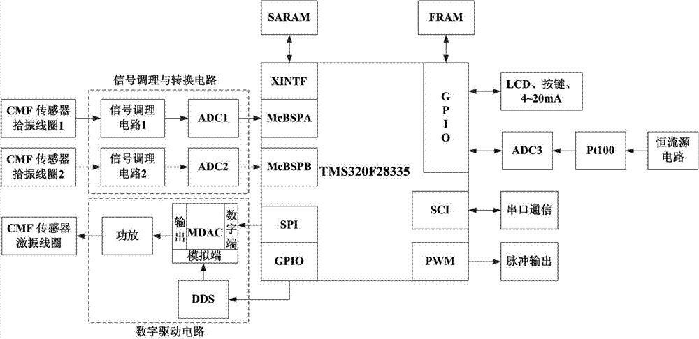
[0031] The block diagram of the hardware structure of the present invention is as figure 1 As shown, including DSP chip, signal conditioning and conversion circuit, digital drive circuit, constant current source circuit, Pt100, ADC3, externally expanded SRAM, externally expanded ferroelectric memory (FRAM), LCD, keys, serial communication, 4~20mA and Pulse output, power module and other components. Among them, the signal conditioning circuit 1, ADC1, signal conditioning circuit 2, and ADC2 form a signal conditioning and conversion circuit, which are connected with the pickup coil 1 and pickup coil 2 of the Coriolis mass flowmeter, and receive, condition and convert the output speed of the pickup coil Signal; DDS, MDAC, and power amplifier form a digital drive circuit to complete the synthesis and output of drive signals.

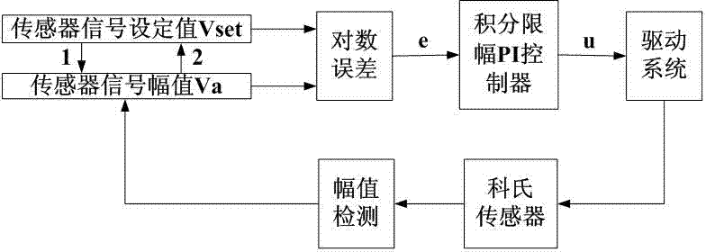
[0032] The working process of the present invention is as figure 2 shown. After the system is powered on, the DSP first completes the initialization of ...


PUM


Abstract

The invention relates to a control method for a coriolis mass flow tube with variable sensor signal setting value. The control method for the coriolis mass flow tube with variable sensor signal setting value takes the DSP as the core and adopts the control method of variable sensor signal setting value based on the DDS and MDAC for automatically tracking the sensor signal amplitude, and the stable vibration can be kept for the floe tube at the time of two-phase flow. The sensor signal setting value is flexibly and effectively adjusted according to the damping ratio change of the flow tube at the premise of meeting industrial explosion-proof requirements, the drive gain has desaturation, the stable and high-level vibration is kept for the flow tube, the stable sensor signal with small amplitude fluctuation is obtained and the signal fluctuation during the two-phase flow measuring process can be reduced.

Description

technical field [0001] The invention belongs to the field of flow detection, and in particular relates to a control method of a Coriolis mass flow tube for the situation that the damping ratio of the flow tube changes sharply during gas-liquid two-phase flow measurement. Background technique [0002] The Coriolis mass flowmeter is used for direct measurement of fluid mass flow, with high measurement accuracy and good repeatability, and it can also simultaneously realize the measurement of fluid volume flow, density, temperature and other parameters under different fluid conditions, and has a wide range of applications prospect. The accurate measurement of the Coriolis mass flowmeter is based on the premise of stable amplitude vibration of the flow tube. When the Coriolis mass flowmeter is tested at the factory, a single-phase water flow calibration experiment is required to determine the best stable vibration amplitude of the flow tube. . The flow tube vibrates at the opti...

Claims


Application Information

Patent Timeline
IPC IPC(8): G01F1/84
Inventor 徐科军陶波波侯其立石岩董帅刘铮
Owner HEFEI UNIV OF TECH
Learn More