Method for lowering detecting dose of radiation imaging system

A ray and ray source technology, which is applied in the field of nuclear technology applications, can solve the problems of increasing radiation safety protection structure, large detection dose, and low detection efficiency, and achieve the effect of reducing the number of rays, reducing radiation dose, and ensuring image quality

Inactive Publication Date: 2015-04-08
TSINGHUA UNIV
View PDF4 Cites 4 Cited by
  • Summary
  • Abstract
  • Description
  • Claims
  • Application Information

AI Technical Summary

Problems solved by technology

[0003] Due to the large thickness of the sheet-like rays passing through the detection channel, the detection dose is relatively large. Therefore, when this detection system is working, the personnel on the vehicle must get off the vehicle and pass outside the detection channel, and the vehicle is dragged by the traction mechanism or dragging device. In the detection channel, or when the vehicle is not moving, the detection gantry straddles the vehicle and sweeps over the inspected vehicle. The detection speed is generally 6-18m / min, that is, 0.36-1.08km / h, and the pass rate is about 10-30 vehicles / h, the detection efficiency is low, and the dragging device or door frame guide rail is required, and the equipment is complicated
At the same time, it is also necessary to set up a special rear collimator, and the radiation safety control area on both sides of the gantry is relatively large, and a radiation safety protection structure needs to be added, which further increases the complexity of the equipment and the processing cost

Method used


Image

  • Method for lowering detecting dose of radiation imaging system
  • Method for lowering detecting dose of radiation imaging system

Examples


Embodiment Construction

[0020] The present invention will be described below in conjunction with the accompanying drawings.

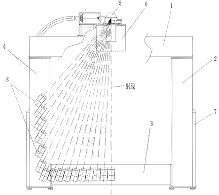
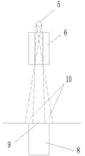
[0021] figure 1 It is a radiation imaging inspection system for inspecting vehicles. Such as figure 1 As shown, the detection system includes a frame, a radiation source, a front collimator, and an array detector. The frame is a rigid frame structure, which is formed by connecting the upper beam 1, the right column 2, the lower beam 3, and the left column 4. The radiation source 5 and the front collimator 6 are installed and fixed on the upper beam 1 and aligned with the upper beam 1 . The array detector is composed of several detectors 8, and each detector 8 may contain several detector units or only one detector unit; Arranged so that the formed array detectors are U-shaped as a whole; each detector 8 is respectively installed in the cavities in the left column 4, the lower beam 3, and the right column 2.

[0022] Of course, it is also possible to adopt a structure in w...


PUM


Abstract

The invention discloses a method for lowering detecting dose of a radiation imaging system. The system comprises a ray source, a front collimator and an array detector, wherein a detecting channel for passing through a to-be-detected object is formed between the front collimator and the array detector; the front collimator is used for collimating rays emitted by the ray source into a sheet fan-shaped beam; the sheet fan-shaped beam penetrates through the detecting channel and then is received and imaged through the array detector; the width of a complete shadow area of the sheet fan-shaped beam, when the sheet fan-shaped beam reaches an incident window of each detector in the corresponding array detector, is matched with the width of the ray incident window of the detector. The width of the incident window area of the sheet fan-shaped beam is matched with the width of the ray incident window of the detector through the front collimator, so that not only can the rays of the complete shadow area be effectively utilized to scan and image, reduce useless rays entering the detector and guarantee the image quality, but also the quantity of rays radiated on the detected object can be reduced as much as possible to lower the detecting dose.

Description

technical field [0001] The invention belongs to the field of nuclear technology applications, and specifically relates to a method for reducing the detection dose of transmission radiation imaging systems widely used in customs, airports, wharves, stations, road checkpoints, etc., for goods, trucks, containers, etc. at present. Background technique [0002] Radiation imaging detection systems for goods, trucks, containers, etc. at customs, airports, docks, and stations are usually composed of a ray source, a front collimator, a rear collimator, and a detector. The rays emitted by the ray source pass through the front collimator After being collimated into a sheet fan beam, it passes through the object to be inspected in the detection channel and is received and imaged by the array detector. In order to ensure that the detector can receive radiation reliably, the thickness of the sheet fan beam is often much larger than the width of the detector’s incident window For this...

Claims


Application Information

Patent Timeline
Patent Type & Authority Applications(China)
IPC IPC(8): G01T1/08
Inventor 李立涛王立强谈春明童建民黄毅斌刘金汇王振涛郭肖静邢桂来郑健
Owner TSINGHUA UNIV
Why Eureka
Try Eureka