
Method and system for dynamically-trimmed spot scanning for ion therapy

a dynamically trimmed, spot scanning technology, applied in radiation therapy, x-ray/gamma-ray/particle irradiation therapy, radiation therapy, etc., can solve the problems of increasing the difficulty in preventing radiation damage to the healthy tissue, and limiting factors such as radiation damage caused by the exiting dose through healthy tissu

Active Publication Date: 2016-07-14
UNIV OF IOWA RES FOUND
View PDF6 Cites 34 Cited by
  • Summary
  • Abstract
  • Description
  • Claims
  • Application Information

AI Technical Summary

Benefits of technology

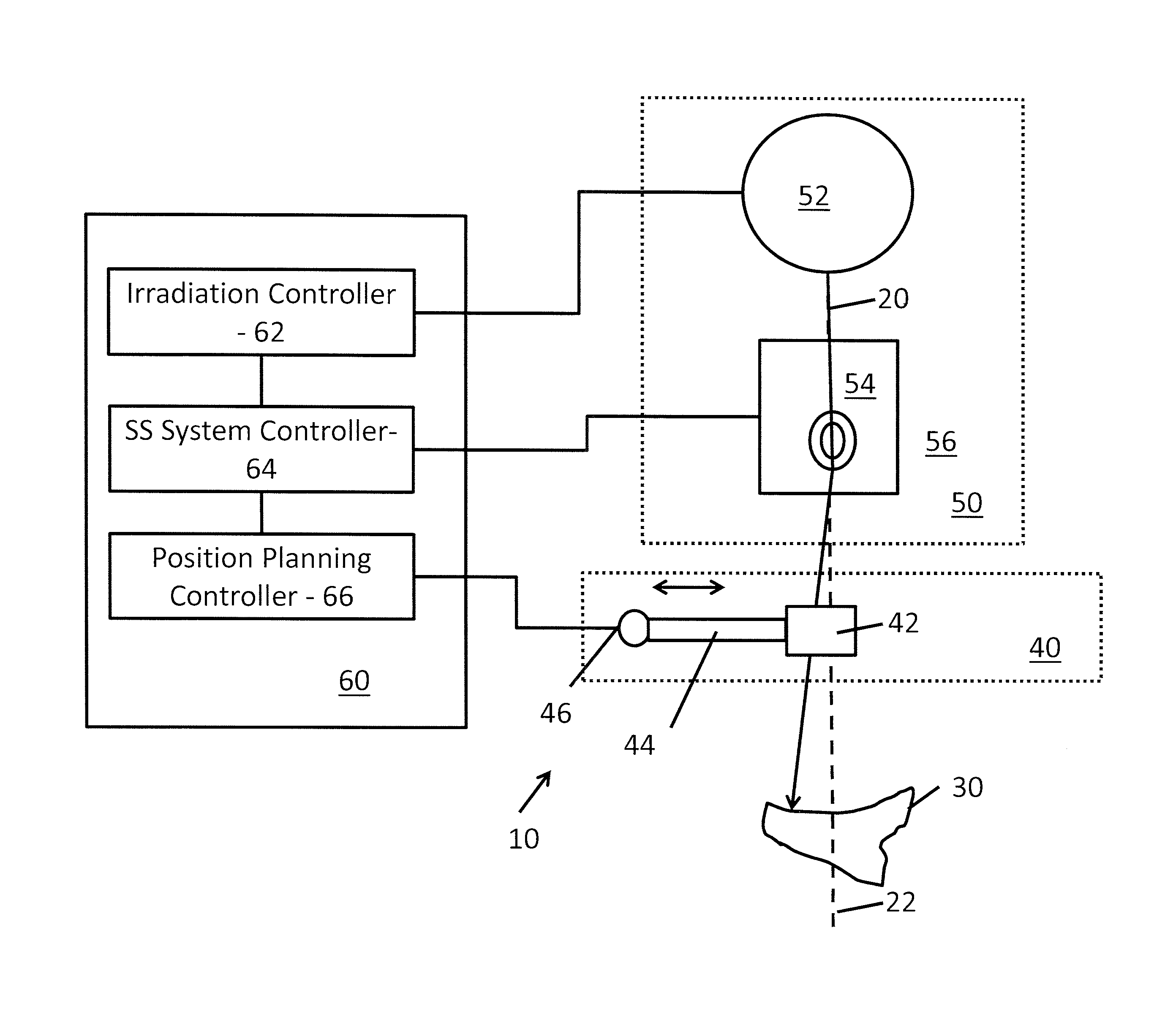
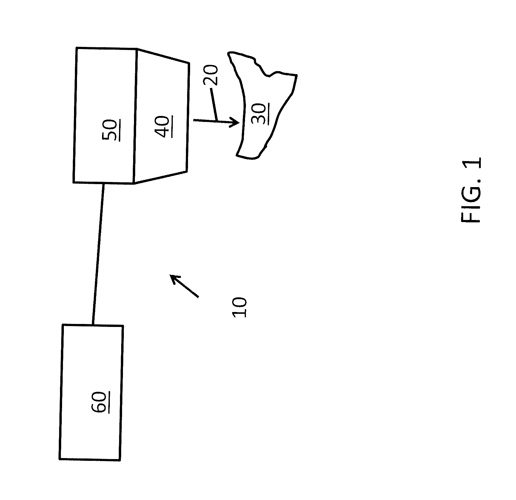
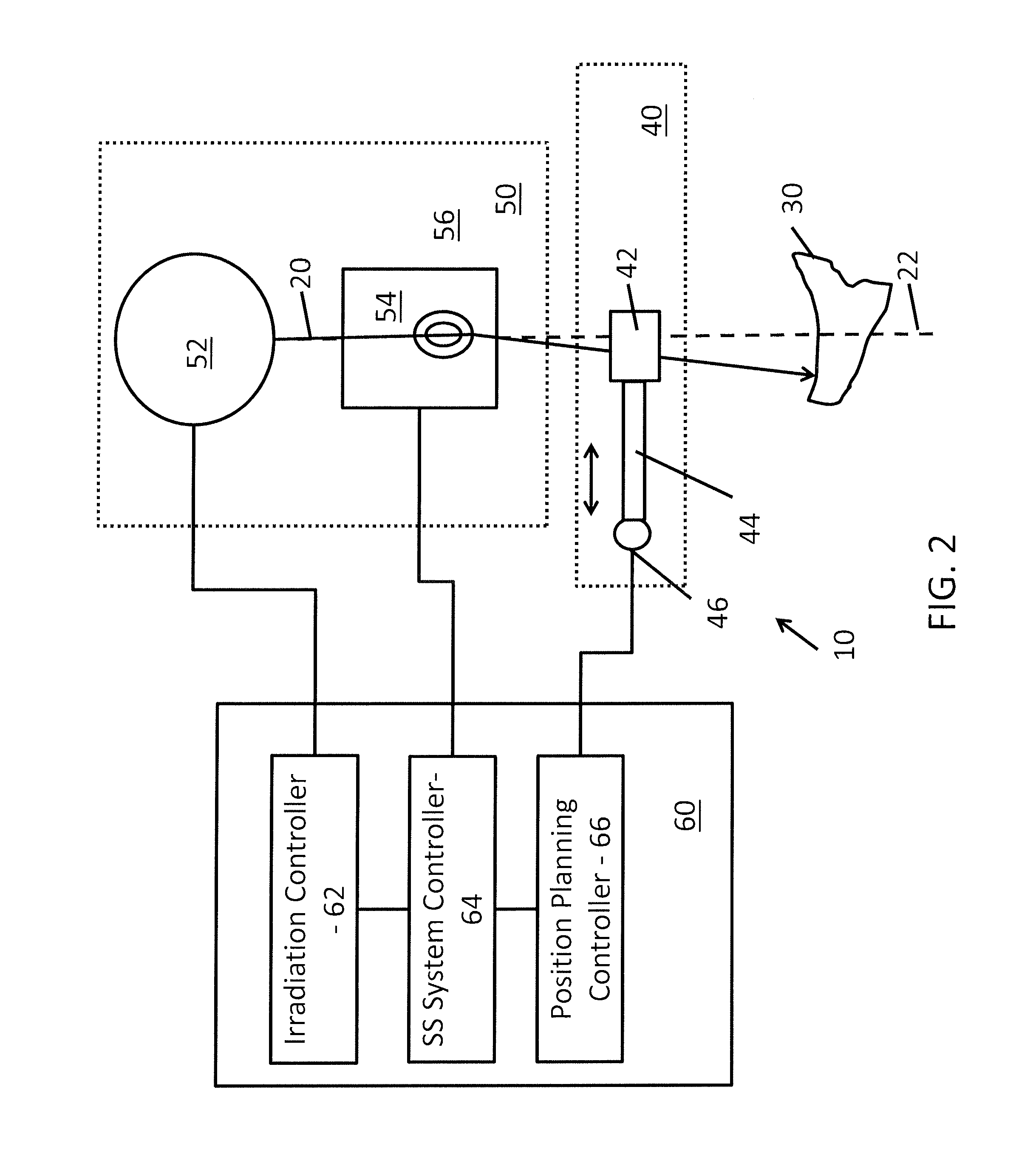
The invention is a system and process for improving particle radiation therapy by reducing the delivery of dose outside the target boundary. It uses a first and second axes of motion to allow for the same at least one trimmer to be moved to various pre-defined positions for intercepting the pencil beam. The DTC can be small enough to position the trimmers within several centimeters of the patient's skin, even when treating sites such as the head and neck. The ability to be able to position the trimmers in various positions multiple times allows for a minimal number of trimmers to be used, reducing the overall size of the DTC. These technical effects improve the effectiveness and safety of particle radiation therapy.

Problems solved by technology

However, photon therapy comes with several complications.
The exiting of the photon beam or dose through the healthy tissue increases the difficulty in preventing radiation damage to the healthy tissue.
The radiation damage caused by the exiting dose through healthy tissue also is a limiting factor when designing an effective tumor treatment plan.
Additionally, in SS, the beam intensity, when averaged over time, is not required to be uniform.
As a result, proton SS is superior to photon therapy in integral dose delivered and inferior to conventional proton therapy in dose delivered lateral to the tumor for low-energy treatments.
A patient specific collimator means an individual collimator for each patient has to be constructed, adding to the overall cost of treatment.
MLCs have been used with pencil beam spot scanning, but MLCs are complex to develop and require a lot of space such that MLCs are prevented from being positioned in a very close proximity to the patient.
In addition, the weight of such an MLC requires a strong mechanical structure to support it.

Method used


Image

  • Method and system for dynamically-trimmed spot scanning for ion therapy
  • Method and system for dynamically-trimmed spot scanning for ion therapy
  • Method and system for dynamically-trimmed spot scanning for ion therapy

Examples


Embodiment Construction

[0059]In the following detailed description of the preferred embodiments, reference is made to the accompanying drawings, which form a part hereof, and within which are shown by way of illustration specific embodiments by which the invention may be practiced. It is to be understood that other embodiments may be utilized and structural changes may be made without departing from the scope of the invention.

[0060]As used in the specification and the appended claims, the singular forms “a,”“an” and “the” include plural referents unless the context clearly dictates otherwise. Ranges may be expressed herein as from “about” one particular value, and / or to “about” another particular value. When such a range is expressed, another embodiment includes from the one particular value and / or to the other particular value. Similarly, when values are expressed as approximations, by use of the antecedent “about,” it will be understood that the particular value forms another embodiment. It will be furt...


PUM


Abstract

A spot scanning (SS) ion therapy system configured for dynamic trimming of an ion particle pencil beam to reduce the amount of the radiation dosage outside of a target boundary.

Description

CLAIM OF PRIORITY[0001]This application claims priority from U.S. Provisional Patent Application No. 61 / 843,092 filed on Jul. 5, 2013, U.S. Provisional Patent Application No. 61 / 900,455, filed on Nov. 6, 2013, and U.S. Provisional Application No. 61 / 946,074 filed on Feb. 28, 2014, all of which are relied upon and incorporated herein in their entirety by reference.BACKGROUND OF THE INVENTION[0002]1. Technical Field[0003]The invention relates to the field of charged particle radiation therapy. More specifically, the invention relates to the field of spot scanned ion therapy. More specifically, the invention relates to a charged particle system for the irradiation of a target of tissues that may be cancerous. The invention also relates to a method for irradiation of a target with a particle pencil beam.[0004]2. Related Art[0005]In charged particle radiation therapy, a number of irradiation techniques are known today. The most common form of radiation therapy currently is photon therapy...

Claims


Application Information

Patent Timeline
Patent Type & Authority Applications(United States)
IPC IPC(8): A61N5/10
CPCA61N5/1043A61N5/1082A61N2005/1095A61N2005/1087A61N2005/1074A61N5/103
Inventor FLYNN, RYANHYER, DANIELWANG, DONGXUHILL, PATRICKCLAEREBOUDT, YVES
Owner UNIV OF IOWA RES FOUND
Learn More