Design method for energy-saving mode of television system

A technology of TV system and energy-saving mode, applied in the field of TV, can solve the problem of not achieving the purpose of energy saving or zero energy consumption, etc.

Inactive Publication Date: 2015-04-08
GUANGDONG CHANGHONG ELECTRONICS
View PDF4 Cites 3 Cited by
  • Summary
  • Abstract
  • Description
  • Claims
  • Application Information

AI Technical Summary

Problems solved by technology

But from the point of view of energy consumption, these standby types have not

Method used


Image

  • Design method for energy-saving mode of television system

Examples


Embodiment Construction

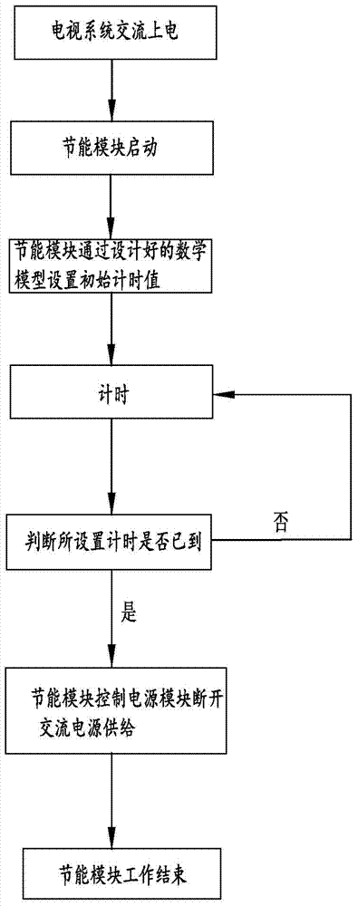
[0021] refer to figure 1 Shown, is the design method of a kind of TV system energy-saving mode of the present invention, comprises the following steps

[0022] A. Create a TV system energy-saving module;

[0023] B. The TV system is powered on by AC, and the energy-saving module starts;

[0024] C. The energy-saving module of the TV system sets the initial timing value through the designed mathematical model; the core program of the energy-saving module of the TV system is the timing module.

[0025] D. Timing;

[0026] E. If the set timing has not arrived, continue to run step D normally;

[0027] F. If the set time has come, the energy-saving module controls the power supply module to cut off the AC power supply, and ends the energy-saving control mode.

[0028] Wherein, there is a switch circuit between the input end of the AC power supply and the TV system power module in the step F, and the energy-saving module controls the switch circuit to cut off the AC power suppl...


PUM


Abstract

The invention discloses a design method for the energy-saving mode of a television system. An energy-saving module is added into an original software module of a television; when the television system is powered on by using alternating current, the energy-saving module is started to work; when time counted by a timing mathematical model for the energy-saving module of the television system is reached, the energy-saving module instructs a power supply module switching circuit to switch off the supply of an alternating-current power supply. Therefore, the aim of real energy saving or zero energy consumption is fulfilled.

Description

technical field [0001] The invention relates to a television set, in particular to a design method for an energy-saving mode of a television system. Background technique [0002] Modern TV system technology has solved various energy saving methods of TV system. For example: no signal standby, no operation standby, sleep time has expired standby, secondary power-on standby standby type. However, from the perspective of energy consumption, these standby types have not achieved the true energy saving or zero energy consumption in essence. Contents of the invention [0003] In order to solve the above technical problems, the object of the present invention is to provide a method for designing an energy-saving mode of a TV system. [0004] The technical scheme adopted in the present invention is: [0005] A method for designing an energy-saving mode of a TV system, comprising the following steps [0006] A. Create a TV system energy-saving module; [0007] B. The TV system...

Claims


Application Information

Patent Timeline
IPC IPC(8): H04N5/63H04N21/443
Inventor 胡剑
Owner GUANGDONG CHANGHONG ELECTRONICS
Why Eureka
Try Eureka