Blade ring for turbomachine

A blade ring, axial-flow turbine technology, applied to the components of the pumping device for elastic fluids, the supporting elements of the blades, the mechanical equipment, etc., can solve the problems of rupture risk, wear of the bearing side, installation and disassembly difficulties, etc. , to achieve the effect of low price, reduced wear and high work safety

Inactive Publication Date: 2015-04-08
SIEMENS AG
View PDF5 Cites 2 Cited by
  • Summary
  • Abstract
  • Description
  • Claims
  • Application Information

AI Technical Summary

Problems solved by technology

Mounting under prestress causes unfavorable wear and wear on the load side, which increases the risk of rupture
Furthermore, in an upstream stage of an axially through-flow compressor, ie in the case of large blades which require a particularly large prestressing force, mounting and dismounting of the blades in the event of maintenance is difficult

Method used


Image

  • Blade ring for turbomachine
  • Blade ring for turbomachine
  • Blade ring for turbomachine

Examples


Embodiment Construction

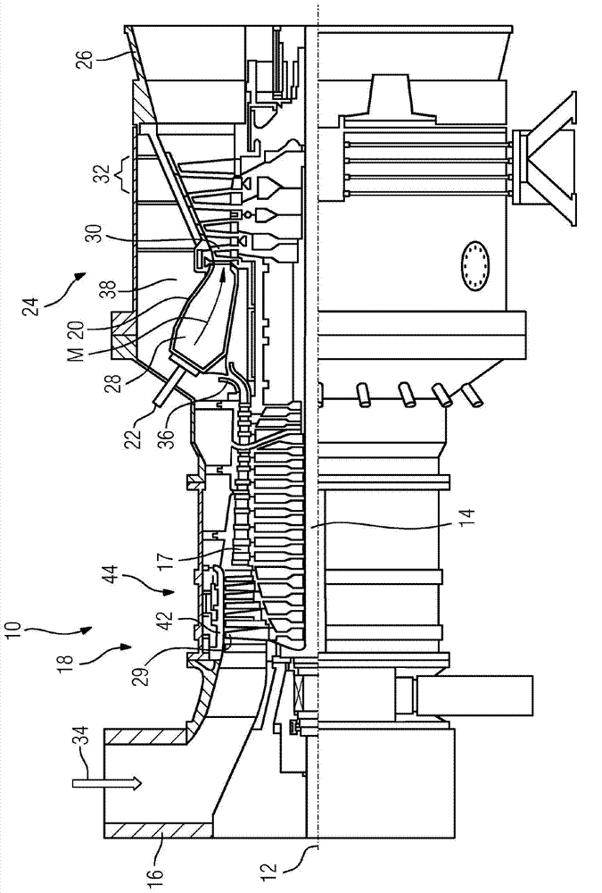
[0025] figure 1 A partial longitudinal section of a stationary gas turbine 10 is shown. The gas turbine 10 internally has a rotor 14 mounted in rotation about an axis of rotation 12 , which is also referred to as a turbine rotor. Arranged in succession along the rotor 14 is a suction housing 16 , a compressor 18 , a torus-shaped annular combustion chamber 20 with a plurality of burners 22 arranged rotationally symmetrically to one another, a turbine unit 24 and a turbine output housing 26 .

[0026]The compressor 18 comprises an annular compressor channel with compressor stages arranged successively in series therein, consisting of a rotor blade ring and a guide blade ring 44 . The rotor blades 17 arranged on the rotor 14 are carried by the rotor disk and lie opposite the outer channel wall 42 of the compressor channel with their freely terminating blade tips 29 . The compressor channel opens into a plenum 38 via a compressor output diffuser 36 . Arranged in the plenum is a...


PUM


Abstract

The invention relates to a blade ring (44) for an axial turbomachine, comprising a blade carrier (46) with a number of retaining grooves (21) and with a corresponding number of blades (27), the blade roots of which are inserted into the retaining grooves (21), wherein the blades (27), on the underside (33) thereof facing toward a groove base (35) of the retaining groove (21), have a recess (37), the base (59) of which recess is at least partially obliquely inclined relative to the groove base (35) of the retaining groove (21) and in which recess there is arranged in each case one wedge-shaped clamping element (47) for pressing the blade root against the support flanks (23). To enable the blade (27) to be mounted in the retaining groove (21) without a preload and to provide a blade ring (44) which can be used in operation without a screw connection, it is provided that a spring element (55) is provided in each recess (37), the spring force of which spring element acts on the respective wedge-shaped clamping element (47) along the retaining groove (21), and that means are provided with which the wedge-shaped clamping element (47) can, for the mounting of the blade (27) in the retaining groove (21) without a preload, be displaced temporarily into a position in which the blade root (31) is seated in the retaining groove (21) with play.

Description

technical field [0001] The invention relates to a blade ring for an axial turbomachine, comprising a blade carrier with a plurality of holding grooves for the blades—with a load side—and a corresponding number of The blade of the blade, the blade root of the blade corresponding to the holding groove is inserted into the holding groove, wherein the blade has a recess on the underside of the root of the blade facing the groove bottom of the holding groove, and the bottom surface of the recess is at least Partially inclined with respect to the groove bottom of the holding groove, wedge-shaped clamping elements are respectively arranged in the recesses to press the blade root onto the load side. Background technique [0002] A similar subject matter is known, for example, from EP 1 892 380 A1. According to the fastening of the compressor rotor blades proposed therein to the rotor, two wedges are provided for each rotor blade between the underside of the blade root and the groov...

Claims


Application Information

Patent Timeline
Patent Type & Authority Applications(China)
IPC IPC(8): F01D5/32
CPCF04D29/322F01D5/3007F01D5/323F01D5/14F01D5/32
Inventor 迪米特里·塞尔默
Owner SIEMENS AG
Why Eureka
Try Eureka