Illumination device, display device, and television reception device

A lighting device and light source technology, which is applied in cooling/heating devices of lighting devices, lighting devices, televisions, etc., can solve problems such as light source damage, achieve the effect of ensuring heat dissipation and improving incident efficiency

Inactive Publication Date: 2015-04-08
SHARP KK
View PDF8 Cites 5 Cited by
  • Summary
  • Abstract
  • Description
  • Claims
  • Application Information

AI Technical Summary

Problems solved by technology

However, when the light source is too close to the light incident surface, the light incident surface may hit the light source due to thermal expansion of the light guide plate and damage the light source.

Method used


Image

  • Illumination device, display device, and television reception device
  • Illumination device, display device, and television reception device
  • Illumination device, display device, and television reception device

Examples


Embodiment approach 1

[0040] Embodiment 1 will be described with reference to the drawings. In this embodiment, the liquid crystal display device 10 is illustrated. In addition, X-axis, Y-axis, and Z-axis are shown in part of each drawing, and description is made so that each axis direction is the direction common to each drawing. The Y-axis direction is consistent with the vertical direction, and the X-axis direction is consistent with the horizontal direction. In addition, unless otherwise specified, descriptions about up and down are based on the vertical direction.

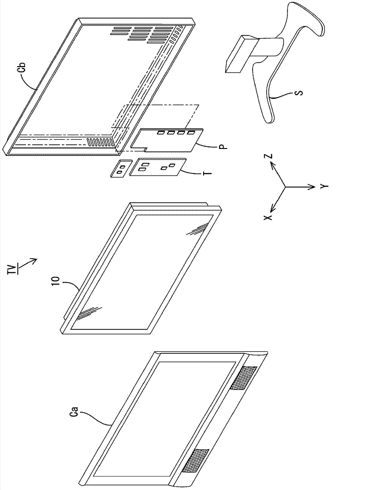
[0041] The television receiver TV includes a liquid crystal display device (an example of a display device) 10 , front and rear cases Ca, Cb that sandwich the liquid crystal display device 10 , a power supply P, a tuner T, and a stand S. Additionally, the figure 2 The upper side shown in the figure is set as the front side, and the lower side in the figure is set as the back side. Such as figure 2 As shown, the liquid crysta...

Embodiment approach 2

[0062] Embodiment 2 will be described with reference to the drawings. In the second embodiment, the mounting form of the LED 128 on the LED substrate 130 is different from that in the first embodiment. The other configurations are the same as those in Embodiment 1, and therefore descriptions of the configurations, operations, and effects are omitted. In addition, in Figure 6 and Figure 7 in, respectively image 3 and Figure 4 The portions where the numeral 100 is added to the reference numerals are the same as those described in the first embodiment.

[0063] In the backlight unit 124 of Embodiment 2, as Figure 6 and Figure 7 As shown, the LED board 130 is configured to include only the heat dissipation portion 130 a without the mounting portion 30 b described in the first embodiment. In addition, the LED 128 is erected on the opposite surface 130 a 1 of the heat dissipation portion 130 a and not located behind the opposite surface 120 c of the light guide plate 12...

Embodiment approach 3

[0065] Embodiment 3 will be described with reference to the drawings. In the third embodiment, the structure of attaching the opposite surface 230 a 1 of the LED substrate 230 to the opposite surface 220 c of the light guide plate 220 is different from that in the first embodiment. The other configurations are the same as those in Embodiment 1, and therefore descriptions of the configurations, operations, and effects are omitted. In addition, in Figure 8 in, will Figure 4 The portions where the numeral 200 is added to the reference numerals are the same as those described in the first embodiment.

[0066] In the backlight unit 224 of Embodiment 3, as Figure 8 As shown, a step 230c is provided on a part of the facing surface 230a1 of the heat dissipation portion 230a of the LED substrate 230 , whereby a part of the heat dissipation portion 230a is close to the facing surface 220c of the light guide plate 220 . In addition, an adhesive tape 238 is disposed between the opp...


PUM


Abstract

This backlight device (24) is provided with: an LED (28); a light guide plate (20) that guides the light from the LED (28) and that has a light exit surface (20b) provided to the obverse surface thereof, a reverse surface (20c) provided to the plate surface at the reverse side from the light exit surface (20b), and a light entrance surface (20a) provided to the two lateral surfaces that form the long sides, the light entrance surface (20a) being disposed in a form facing the LED (28); a radiating member (36) that has radiating properties and that has at least a plate-shaped section (36a) disposed at the reverse surface (20c) side; an LED substrate (30) that has a facing surface (30a1) facing the reverse surface (20c), has an attachment section (30b) forming a portion thereof to which the LED (28) is attached, and is disposed on the plate-shaped section (36a) in a form that can slide in a direction perpendicular to the light entrance surface (20a); and an adhesive tape (38) that is disposed between the reverse surface (20c) and the facing surface (30a1) and that pastes the LED substrate (30) to the light guide plate (20).

Description

technical field [0001] The present invention relates to an illuminating device, a display device and a television receiving device. Background technique [0002] In recent years, the display elements of image display devices such as television receivers are changing from conventional Braun tubes to thin display devices using thin display elements such as liquid crystal panels and plasma display panels, making image display devices thinner. possible. Since a liquid crystal panel used in a liquid crystal display device does not emit light by itself, a backlight device is additionally required as an illumination device. As an example of such a backlight device, there is known an edge-light type backlight device in which a light incident surface is provided on a side surface of a light guide plate and planar light sources such as LEDs are arranged on the side surface of the light guide plate. [0003] In an edge-light type backlight device, the light incident efficiency is imp...

Claims


Application Information

Patent Timeline
Patent Type & Authority Applications(China)
IPC IPC(8): F21S2/00F21V29/50G02F1/13357F21Y101/02
CPCG02B6/0068G02B6/0085G02B6/0073G02B6/0091H04N5/64G02B6/0031G02B6/0065G02B6/0086
Inventor 清水敬治
Owner SHARP KK
Why Eureka
Try Eureka