Supercharge Your Innovation With Domain-Expert AI Agents!

Temperature Sensor

A temperature sensor, sensor technology, applied in thermometers, resistors with negative temperature coefficients, instruments, etc., can solve the problems of difficult temperature detection, damage to the surface of the roller, poor responsiveness, etc., to achieve good B constant, accurate temperature measurement, Highly responsive effects

Active Publication Date: 2017-08-29
MITSUBISHI MATERIALS CORP
View PDF3 Cites 0 Cited by
  • Summary
  • Abstract
  • Description
  • Claims
  • Application Information

AI Technical Summary

Problems solved by technology

[0009] That is, in the technology described in Patent Document 1, a spherical thermistor or the like is used as the thermal element, but in this case, it is spherical or elliptical about 1 mm in shape, and therefore it is difficult to accurately perform point contact with the heating roller. temperature detection of , and has the undesired case of being less responsive due to the volume
Also, due to point contact, there is a possibility of damage to the rotating roller surface
[0010] In addition, in the technology described in Patent Document 2, since a thin film thermistor is used as a heat sensitive element, it can be in surface contact with the heating roller, but if it includes an insulating substrate or a lead part constituting the thin film thermistor, it still has a bulky , so there is a problem of poor responsiveness

Method used


Image

  • Temperature Sensor
  • Temperature Sensor
  • Temperature Sensor

Examples


Embodiment

[0100] Next, regarding the temperature sensor involved in the present invention, refer to Figure 11 to Figure 19 The results of evaluation based on the examples prepared according to the above-mentioned embodiment will be specifically described.

[0101]

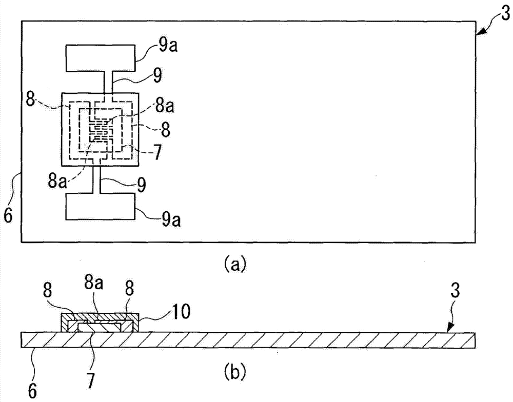
[0102] Examples and comparative examples for evaluating the thermistor material layer (thin film thermistor part 7) of the present invention were prepared as follows Figure 11 Element 121 is shown for film evaluation.

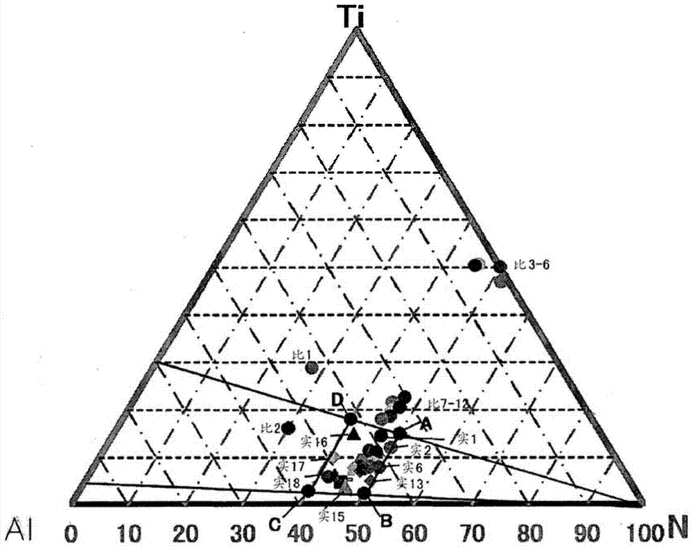
[0103] First, by the reactive sputtering method, Ti-Al alloy targets with various composition ratios were used to form Si substrates S with a thickness of Thin film thermistor part 7 of 500nm metal nitride material. The sputtering condition at this time is, reaching the vacuum degree: 5×10 -6 Pa, sputtering gas pressure: 0.1 ~ 1Pa, target input power (output power): 100 ~ 500W, in the mixed gas atmosphere of Ar gas + nitrogen gas, and change the nitrogen gas fraction to 10 ~ 100%.

[0104] Next, a Cr ...


PUM

PropertyMeasurementUnit
thicknessaaaaaaaaaa
thicknessaaaaaaaaaa
thicknessaaaaaaaaaa

Abstract

The temperature sensor is provided with a pair of lead frames, a sensor portion connected to the pair of lead frames, and an insulating holding portion which is fixed to the pair of lead frames and holds the lead frames. The sensor portion is provided with an insulating film; a thin film thermistor portion formed as a pattern on the surface of the insulating film with a thermistor material; a pair of interdigitated electrodes formed as patterns having multiple comb portions and facing each other on the thin film thermistor portion; and a pair of pattern electrodes connected to the pair of interdigitated electrodes and formed as patterns on the surface of the insulating film. The pair of lead frames is extended and adhered to the surface of the insulating film disposing the thin film thermistor portion therebetween and is connected to the pair of pattern electrodes.

Description

technical field [0001] The present invention relates to a temperature sensor suitable for measuring the temperature of a heating roller of a copier, a printer, etc., and having excellent responsiveness. Background technique [0002] Usually, a temperature sensor is placed in a contact state in order to measure the temperature of a heating roller used in a copier or a printer. As such a temperature sensor, for example, Patent Documents 1 and 2 propose a temperature sensor including: a pair of lead frames; a heat sensitive element arranged and connected between these lead frames; an end portion of the frame; and a film sheet disposed on one side of the lead frame and the thermal element and in contact with the heating roller. [0003] Such a temperature sensor detects temperature by contacting the surface of the heating roller with the elastic force of the lead frame. [0004] In addition, in the above-mentioned Patent Document 1, a spherical thermistor or a chip thermistor ...

Claims


Application Information

Patent Timeline
Patent Type & Authority Patents(China)
IPC IPC(8): G01K7/22H01C7/04
Inventor 长友宪昭稻场均田中宽竹岛一太
Owner MITSUBISHI MATERIALS CORP
Features
  • R&D
  • Intellectual Property
  • Life Sciences
  • Materials
  • Tech Scout
  • Unparalleled Data Quality
  • Higher Quality Content
  • 60% Fewer Hallucinations
Learn More