Secondary coil of receiver for non-contact charging system

A secondary coil and charging system technology, applied in the direction of electromagnetic wave system, transformer/inductor coil/winding/connection, inductor, etc., can solve the problem of insufficient charging efficiency, increase the size and weight of cellular phones, and increase product costs and other problems to achieve the effect of reducing the reduction of charging efficiency

Inactive Publication Date: 2015-04-08
金宣燮
View PDF17 Cites 10 Cited by
  • Summary
  • Abstract
  • Description
  • Claims
  • Application Information

AI Technical Summary

Problems solved by technology

[0015] However, the "motor control method" and the "multiple primary coil-based method" have disadvantages in that the product cost is relatively increased due to an increase in the number of parts compared to the "magnetic method"
In addition, the motor control method has a limitation that the weight of the primary coil should be limited in order to reduce the load applied to the motor, and the method based on a plurality of primary coils has a problem in that the size of the transmitter is excessively reduced due to the array structure of the primary coil. increase, should limit the size of each coil in the primary coil
However, when the magnetic method is applied to a cellular phone, there are problems in that the size and weight of the cellular phone are increased due to the presence of the magnet, and the applied magnet makes any other magnetic field device (for example, a compass) installed in the cellular phone , gyroscope, etc.) does not work
[0020] However, according to the power transmission control method, although charging efficiency is improved by changing the charging frequency within a range of, for example, 205kHz to 110kHz, and this range is within a range in which induced electromotive force is generated; When deviating, the charging efficiency decreases by up to 20% or more compared to the maximum charging efficiency at, for example, the outermost position where the smallest induced electromotive force is induced
Therefore, there is a limitation that the supplement to the charging efficiency is not sufficiently performed

Method used


Image

  • Secondary coil of receiver for non-contact charging system
  • Secondary coil of receiver for non-contact charging system
  • Secondary coil of receiver for non-contact charging system

Examples


Embodiment Construction

[0045] Hereinafter, the present invention will be described in detail with reference to the accompanying drawings. The detailed examples disclosed herein are for illustrative purposes only and are not intended to limit the scope of the present invention.

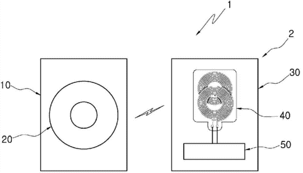
[0046] Such as figure 1 As shown, similar to the conventional non-contact charging system applied to a cellular phone as a representative portable device 2, the non-contact charging system 1 to which the secondary coil 40 of the present invention is applied includes: a transmitter in which the primary coil 20 is installed. 10 (for example, a charging pad); and a receiver 30 (for example, a cellular phone) in which the secondary coil 40 is installed. Hereinafter, a cellular phone will be mainly described as an example of the portable device 2, and the portable device and the cellular phone will refer to the same reference numeral 2 of the drawings.

[0047] As known, in addition to the primary coil 20 and the secondary coi...


PUM

PropertyMeasurementUnit
thicknessaaaaaaaaaa

Abstract

Provided is a secondary coil (40) applied to an electromagnetic induction type non-contact charging system according to the present invention, the secondary coil including: a substrate (41); a first coil 42 stacked on one side of the substrate (41) and having a first internal space (42a) formed in its center; a second coil 43 stacked on the other side of the substrate (41) and having a second internal space (43a) formed in its center; a first additional pattern (44) electrically connected to the first coil (42); and a second additional pattern (45) electrically connected to the second coil (43), wherein the first internal space (42a) and the second internal space (43a) are not vertically aligned, but "are non-overlappingly arranged" to deviate by a predetermined distance in a horizontal direction.

Description

technical field [0001] The present invention relates generally to contactless charging systems, and more particularly to a receiver's secondary coil for a contactless charging system for use in a transmitter's primary coil and a receiver's Electromagnetic induction generated between a secondary coil placed close to the primary coil charges a battery electrically connected to the secondary coil. Background technique [0002] Repeatedly rechargeable batteries have been widely used in place of disposable batteries to power various portable devices as well as cellular phones. Generally, a wired (contact) charging method is widely used in charging a rechargeable battery, but recently a non-contact (wireless) charging method is increasingly used. [0003] Examples of conventional techniques related to non-contact charging of cellular phones are as follows: "Contactless charging system of radio telephone" disclosed in Korean Patent Publication No. 10-1995-0005819 (published on May...

Claims


Application Information

Patent Timeline
Patent Type & Authority Applications(China)
IPC IPC(8): H02J17/00H02J7/00H01F38/14
CPCH02J7/025H01F27/2823H04B5/0075H04B5/0037H01F27/28H01F38/14H02J5/005H01F27/2804H02J50/10H02J50/005H02J7/00714H02J50/90
Inventor 金宣燮
Owner 金宣燮
Why Eureka
Try Eureka