
Air conditioning system being able to achieve continuous heating

A technology of air conditioning system and heating mode, applied in refrigerators, refrigeration components, refrigeration and liquefaction, etc., can solve the problems of compressor suction with liquid, indoor mechanism heat effect, wear and other problems, and achieve the effect of easy distribution

Active Publication Date: 2015-04-15
GREE ELECTRIC APPLIANCES INC
View PDF9 Cites 15 Cited by
  • Summary
  • Abstract
  • Description
  • Claims
  • Application Information

AI Technical Summary

Problems solved by technology

The thermal storage and defrosting method adopted by the air conditioning circulation device in the prior art is that the suction end of the compressor merges two parts of refrigerant: one part is the refrigerant that passes through the indoor unit and then the heat storage tank; the other part is the refrigerant that defrosts the outdoor unit, The two streams of refrigerants meet at the suction end of the compressor and return directly to the compressor. At this time, the refrigerant is likely to cause liquid in the suction of the compressor, which will cause wear and tear. In addition, the two-part flow is not easy to control, and the heat of the indoor mechanism is directly affected.

Method used


Image

  • Air conditioning system being able to achieve continuous heating
  • Air conditioning system being able to achieve continuous heating
  • Air conditioning system being able to achieve continuous heating

Examples


Embodiment 1

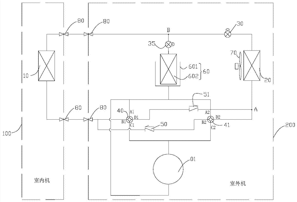
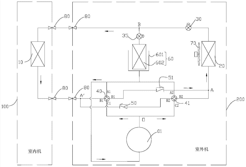
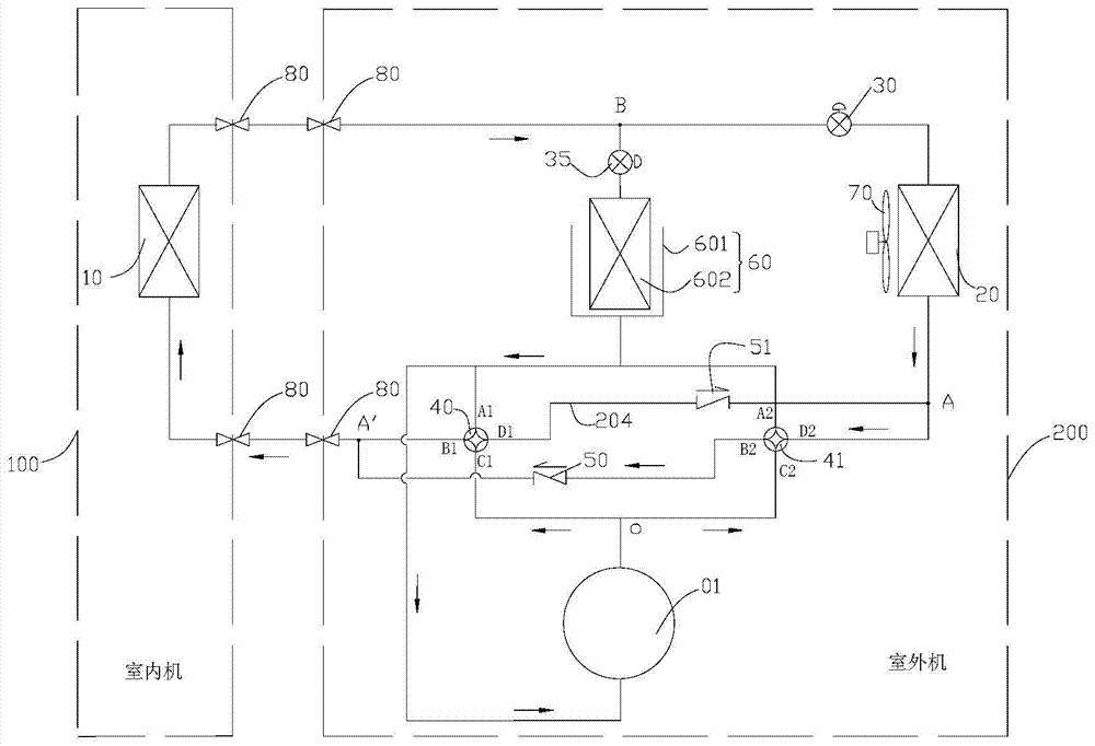
[0041] refer to Figure 1 to Figure 4 , an embodiment of the air conditioning system capable of continuous heating of the present invention includes an indoor unit 100 and an outdoor unit 200, the indoor unit 100 includes an indoor heat exchanger 10, and the outdoor unit 200 includes a compressor 01, an outdoor heat exchanger 20, a throttling The element 30, the switching device and the heat storage device 60; the compressor 01, the switching device, the outdoor heat exchanger 20, the throttling element 30 and the indoor heat exchanger 10 are sequentially connected to form a refrigeration circuit, and the heat storage device is connected in series to the throttling element 30. Between the first end (left end) and the switching device, the second end (right end) of the throttling element 30 communicates with the outdoor heat exchanger 20; the throttling element 30 is an electronic expansion valve or a capillary tube.

[0042] The air conditioning system has a first heating mode...

Embodiment 2

[0053] The difference between the second embodiment and the first embodiment lies in the difference of the switching device, refer to Figure 5 to Figure 8 , in this embodiment, the switching device includes a first three-way valve 61 and a second three-way valve 62, the first three-way valve 61 has first to third valve ports (A3, B3, C3), the second three-way valve The through valve 62 has fourth to sixth valve ports (A4, B4, C4), the first valve port A3 is connected to the indoor heat exchanger 10, and the second valve port B3 is respectively connected to the fifth valve port B4 and the exhaust gas of the compressor 01. end, the third valve port C3 is respectively connected to the sixth valve port C4, the heat storage device 60 and the suction end of the compressor 01, and the fourth valve port A4 is connected to the outdoor heat exchanger 20;

[0054] In the first heating mode, the first valve port A3 is connected to the second valve port B3, the fourth valve port A4 is con...


PUM


Abstract

The invention provides an air conditioning system being able to achieve continuous heating; a compressor, a switching device, an outdoor heat exchanger, a throttle element and an indoor heat exchanger are sequentially connected in order to form a refrigeration loop; a heat accumulation device is cascaded between the first end of the throttle element and the switching device; the second end of the throttle element is communicated with the outdoor heat exchanger; the air conditioning system has a first heating mode and a second heating mode; under the first heating mode, the refrigerant discharged by the compressor sequentially enters the indoor heat exchanger, the throttle element, and the outdoor heat exchanger via the switching device; under the second heating mode, the refrigerant discharged by the compressor passes through the switching device, one path thereof enters the indoor heat exchanger, the other path enters the outdoor heat exchanger; the refrigerant flows out from the outdoor heat exchanger and the indoor heat exchanger enters an air suction end of the compressor via the heat accumulation device. The air conditioning system being able to achieve continuous heating enables the heat pump air conditioner to heat continuously while the air conditioner is working to heat; the flux of refrigerant flows into the indoor heat exchanger and the outdoor heat exchanger are easier to be distributed.

Description

technical field [0001] The invention relates to the refrigeration field, in particular to an air-conditioning system capable of realizing continuous heating. Background technique [0002] Thermal storage and defrosting is a new technology in the field of heating research and product promotion in the industry. The thermal storage and defrosting method adopted by the air conditioning circulation device in the prior art is that the suction end of the compressor merges two parts of refrigerant: one part is the refrigerant that passes through the indoor unit and then the heat storage tank; the other part is the refrigerant that defrosts the outdoor unit, The two streams of refrigerant merge at the suction end of the compressor and return directly to the compressor. At this time, the refrigerant is likely to cause liquid in the compressor suction, which will cause wear and tear. In addition, the two-part flow is not easy to control, and the heat of the indoor mechanism is directly...

Claims


Application Information

Patent Timeline
Patent Type & Authority Applications(China)
IPC IPC(8): F25B29/00F25B41/04F25B41/20F25B41/24
CPCF25B29/003F25B41/20
Inventor 周中华韩雷郭瑞安李潇吴会丽
Owner GREE ELECTRIC APPLIANCES INC
Learn More