Isolator system for a pressure transmitter

An isolation system and transmitter technology, applied in the field of isolation systems, can solve the problems of not inhibiting the rapid response of the pressure sensor, slowing down the pressure sensor, restricting the flow of oil, etc.

Active Publication Date: 2015-04-15
ROSEMOUNT INC
View PDF6 Cites 7 Cited by
  • Summary
  • Abstract
  • Description
  • Claims
  • Application Information

AI Technical Summary

Problems solved by technology

However, narrow passages can restrict oil flow and slow pressure sensor response
It is desirable for the isolation

Method used


Image

  • Isolator system for a pressure transmitter
  • Isolator system for a pressure transmitter
  • Isolator system for a pressure transmitter

Examples


Embodiment Construction

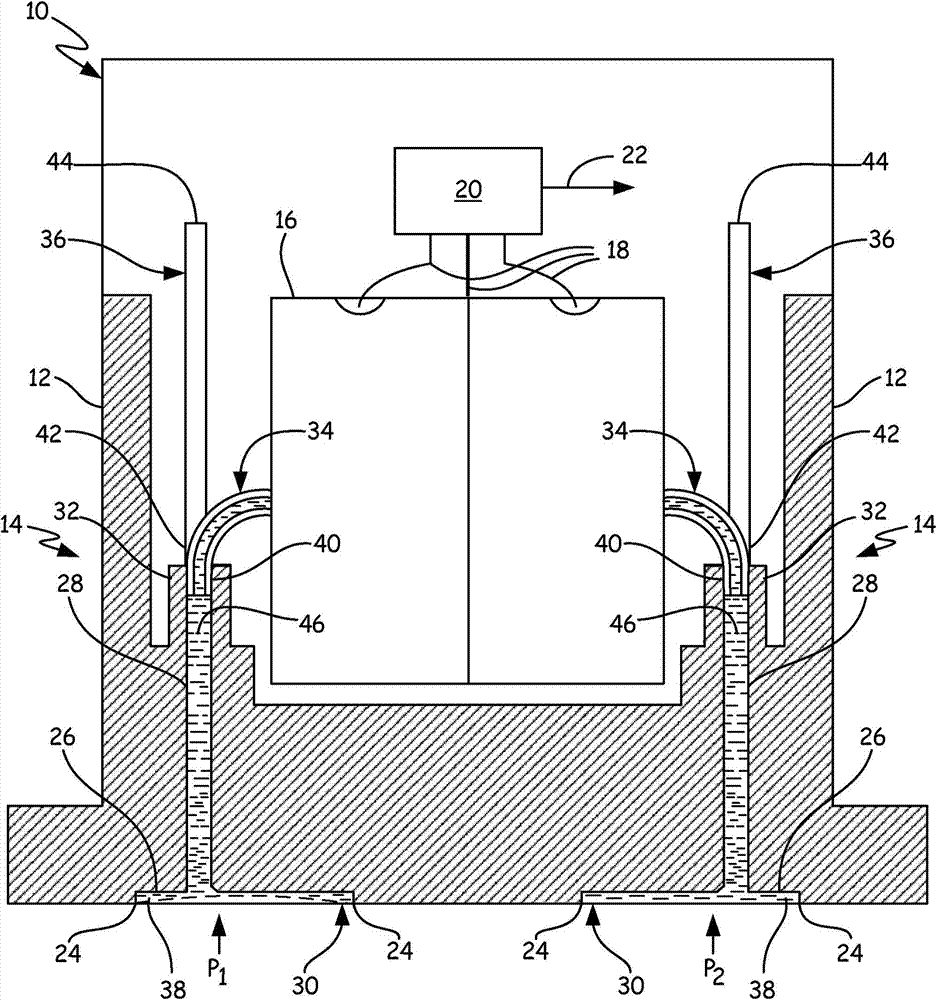
[0011] Embodiments of the present invention provide an isolation system suitable for industrial pressure transmitters. An isolation system embodying the invention employs the improvement of the invention to a pressure transmitter comprising an oil fill tube and a sensor tube shaped to fit together in a single port, as in the US assigned to Rosemount Corporation Described in "PRESSURE TRANSMITTER WITH IMPROVED ISOLATOR SYSTEM" Patent 6,662,662, which is incorporated herein by reference.

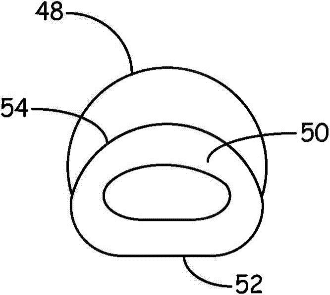
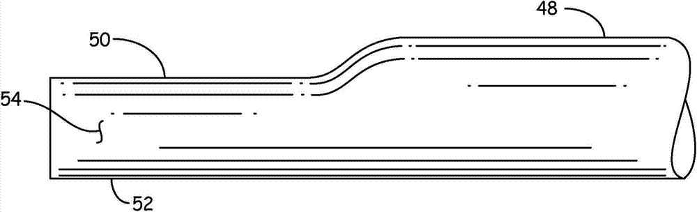
[0012] In an embodiment of the invention, the isolation system is improved by allocating a majority of the total cross-sectional area of ​​the sensor tube and the oil-filled tube to the sensor tube. The larger sensor tube cross-sectional area reduces the flow impedance through the sensor tube without increasing the size of the port or the amount of oil filled in the port. As a result, in operation, the response time between a pressure change at the isolation diaphragm and a pressure change de...


PUM


Abstract

An isolator system for a pressure transmitter includes a port internal to the transmitter, a sensor tube, and a fill tube. The sensor tube is connected to the port to fluidly connect a passageway through a transmitter body to a pressure sensor. The sensor tube includes a first end disposed in the port. The first end has a first cross-sectional area. The fill tube is internal to the transmitter and connected to the port to fluidly connect to the passageway. The fill tube includes a second end disposed in the port. The second end of the fill tube has a second cross-sectional area that is less than the first cross-sectional area of the sensor tube.

Description

technical field [0001] The present invention generally relates to a pressure transmitter for an industrial process. In particular, the invention relates to an isolation system for use in pressure transmitters. Background technique [0002] Isolation systems in pressure transmitters use a relatively inert isolation liquid that couples the pressure from the process fluid to the pressure sensor. This is necessary because pressure sensors are generally not designed to withstand direct contact with the process fluid. A flexible isolating diaphragm separates a barrier liquid, usually silicone oil, from the process fluid. Tubes and channels filled with this silicone oil are used to couple the pressure from the isolation diaphragm to the pressure sensor. The isolation system prevents process fluid from contacting the pressure sensor and interfering with the operation of the pressure sensor. [0003] The oil fill tubes and channels are kept narrow to reduce the amount of oil used...

Claims


Application Information

Patent Timeline
IPC IPC(8): G01L19/00
CPCG01L19/0046
Inventor 罗伯特·C·海德克埃里克·彼得森
Owner ROSEMOUNT INC
Why Eureka
Try Eureka