
An audio signal edge waveform control circuit

An audio signal and control circuit technology, applied in the direction of electrical components, electric pulse generation, pulse generation, etc., to achieve the effect of soft envelope waveform of audio signal, low hardware cost, and solving the effect of rising and falling edge gradients

Active Publication Date: 2018-01-30
HENAN XIRUI MEDICAL ELECTRONICS TECH
View PDF6 Cites 0 Cited by
  • Summary
  • Abstract
  • Description
  • Claims
  • Application Information

AI Technical Summary

Problems solved by technology

[0005] Solved the problem of the rising and falling edge gradient of the medical alarm sound

Method used


Image

  • An audio signal edge waveform control circuit
  • An audio signal edge waveform control circuit
  • An audio signal edge waveform control circuit

Examples


Embodiment 1

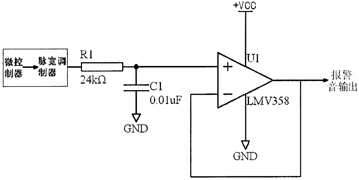
[0021] Such as figure 1 As shown: an audio signal edge waveform control circuit described in this embodiment includes a pulse width modulator unit 001 including a microcontroller, a low-pass filter unit 002 and a final follower unit 003, and the low-pass filter unit 002 is respectively Connect with pulse width modulator unit 001 and follower unit 003 containing microcontroller. The described pulse width modulator unit 001 that contained microcontroller was selected to be a known product, including realizing the pulse width modulator function by single-chip microcomputer, microcontroller, DSP chip, FPGA chip, CPLD chip, etc. hardware configuration. This embodiment selects PIC16F690 and all microcontrollers including pulse width modulators, which can realize the modulation range of 0-100% without dead zone; the low-pass filtering unit 002 includes an RC low-pass filter circuit , the low-pass filter circuit can also be two or more, and the selected ones are also known products ...

Embodiment 2

[0025] Such as Figure 5 As shown: the audio signal edge waveform control circuit described in this embodiment is based on the structure of Embodiment 1, and the final follower unit 003 uses an NPN transistor Q1 instead of the integrated circuit U1 to play the role of final follower. Working principle and embodiment of this embodiment figure 1 The same, which has been explained above and will not be repeated here.

Embodiment 3

[0027] Such as Figure 6 As shown: the audio signal edge waveform control circuit described in this embodiment is based on the structure of Embodiment 1, and the final follower unit 003 uses an N-channel field effect transistor Q1 to replace the integrated circuit U1 to play the final follower effect. Working principle and embodiment of this embodiment figure 1 The same, which has been explained above and will not be repeated here.


PUM


Abstract

An audio signal edge waveform control circuit disclosed by the present invention includes a pulse width modulator unit (001) including a microcontroller, a low-pass filter unit (002) and a follower unit (003). The modulator unit modulates the input signal to generate a modulated wave with a corresponding pulse width. After the modulated wave is filtered by a low-pass filter unit to filter out the high-order harmonics in the modulated wave, an audio signal edge control waveform is formed. The audio signal edge control waveform After the waveform is formed by the following unit, the edge control waveform signal of the audio signal can be output. It effectively solves the problem of the gradient of the rising and falling edges of the medical alarm sound. At the same time, the envelope waveform of the output audio signal can be softer and more delicate, which is more in line with the auditory characteristics of human ears. The circuit has the advantages of simple implementation method and low hardware cost.

Description

technical field [0001] The present invention relates to audio signal edge waveform control technology, in particular to an audio signal edge waveform [0002] Control circuit. Background technique [0003] An industry standard for medical device alarm systems that describes in detail everything from the medical conditions that trigger the audible alarm to the frequency and waveform of the audible alarm. When an alarm occurs on a medical alarm instrument, medical staff expect to be able to infer the urgency, nature, and even cause of the alarm from the sound alarm, so as to take corresponding measures to deal with emergencies. According to the standards, the audio signal is required to have a gradient form, that is, the sound alarm signal is required to have a rising edge and a falling edge. How to make the rising and falling edges of the alarm tone is a problem to be solved. In the prior art, integrated circuit chips (such as DAC conversion chips, etc.) are used to contro...

Claims


Application Information

Patent Timeline
Patent Type & Authority Patents(China)
IPC IPC(8): H03K3/017
Inventor 王勇徐季霞郜时兴葛苒
Owner HENAN XIRUI MEDICAL ELECTRONICS TECH
Learn More