
Method for optimizing uplink capacity and coverage and base station

A technology of capacity and base station, applied in the field of communication, can solve the problems of non-coverage, capacity improvement, and increased interference, etc.

Active Publication Date: 2015-04-15
CHINA TELECOM CORP LTD
View PDF6 Cites 8 Cited by
  • Summary
  • Abstract
  • Description
  • Claims
  • Application Information

AI Technical Summary

Problems solved by technology

[0008] Among them, the cell-level parameter α is mainly used to partially compensate for the path loss, and this parameter mainly controls the balance relationship between edge and center users, while P 0 The setting usually involves the IOT (Interference Over Thermal) in the area and the transmit power of the users in the cell, and the cell parameter P 0 It can increase the PSD (Power Spectral Density) of end users on each PRB (Physical Resource Block, physical resource block), but it also increases the interference to neighboring cells and improves the IOT in the network, so the simple Raise P 0 Does not lead to improved coverage and capacity

Method used


Image

  • Method for optimizing uplink capacity and coverage and base station
  • Method for optimizing uplink capacity and coverage and base station
  • Method for optimizing uplink capacity and coverage and base station

Examples


Embodiment 1

[0223] This embodiment mainly provides a process of optimizing the coverage performance of a cell by using an uplink inclination angle optimization method because the coverage performance of a macro base station configured with an active antenna fails to reach the target value set by the system. The macro base station includes three cells, among which cell 1 triggers coverage optimization and adjustment. where the antenna gain in the vertical plane is:

[0224] A V ( θ ) = - min ( 12 ( θ - φ tilt φ 3 dB ) ...

Embodiment 2

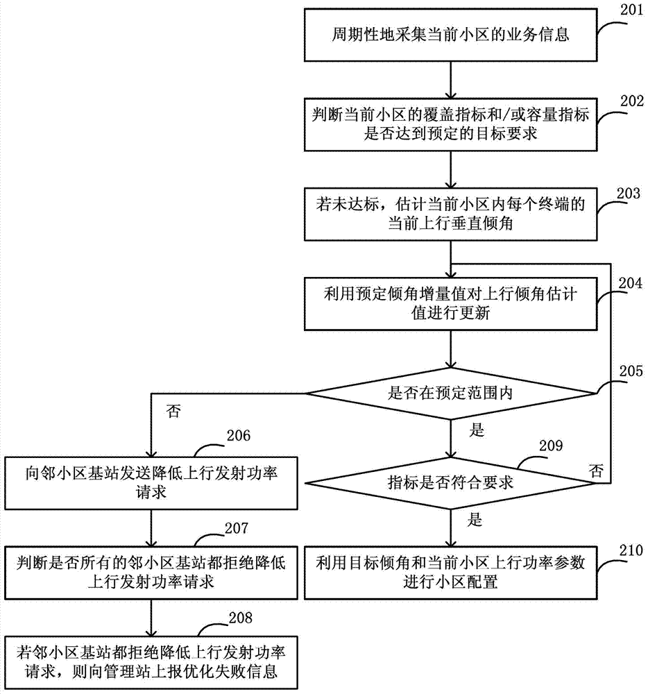
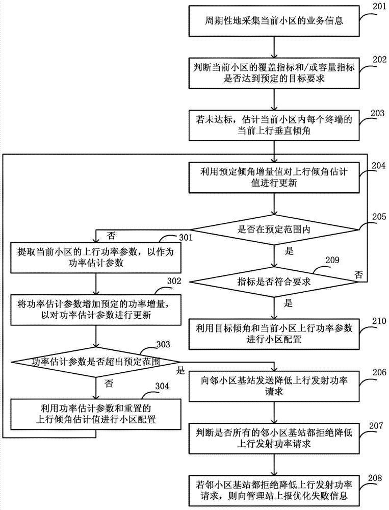
[0243] This embodiment mainly shows that a macro base station equipped with an active antenna cannot find a suitable uplink tilt angle to optimize the coverage performance of the cell because its own coverage performance fails to reach the target value set by the system, and triggers a call to the neighboring cell 4 The process of requesting to reduce the power parameter P0. The macro base station includes three cells, among which cell 1 triggers coverage optimization and adjustment. where the antenna gain in the vertical plane is:

[0244] A V ( θ ) = - min ( 12 ( θ - φ tilt φ 3 ...

Embodiment 3

[0265] This embodiment mainly provides a process in which a small base station configured with an active antenna optimizes the uplink angle and power setting parameter P0 of the cell due to receiving a power reduction request from a neighboring cell, wherein the small base station has only one cell, and It is a cell with omnidirectional coverage, and the cell ID is cell 1. The cell that sends the power down request is a macro cell, and the cell ID is cell 4. For the topology relationship between cell 1 and cell 4, see Figure 9 . where the antenna gain in the vertical plane is:

[0266] A V ( θ ) = - min ( 12 ( θ - φ tilt φ ...


PUM


Abstract

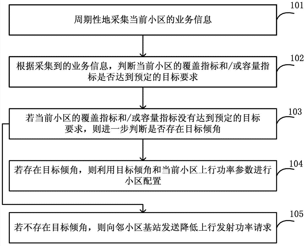
The invention discloses a method for optimizing uplink capacity and coverage and a base station. The method for optimizing uplink capacity and coverage comprises the following steps: judging whether the coverage index and / or capacity index of a current cell meets a predetermined target requirement according to periodically-acquired service information; if the predetermined target requirement is not meet, further judging whether a target inclination angle exists in a predetermined cell uplink vertical inclination angle range or not; if the target inclination angle exists, performing cell configuration by using the target inclination angle and the uplink power parameter of the current cell; and otherwise, sending an uplink transmitting power lowering request to a neighboring cell base station in order that the coverage index and the capacity index of the current cell meet the predetermined target requirement through reduction of interference to a neighboring cell. An LTE (Long Term Evolution) cell configured with an active antenna reaches desired coverage and capacity targets in different interference environments, and uplink interference to the neighboring cell is reduced, so that service quality in the uplink direction of a whole network is enhanced.

Description

technical field [0001] The invention relates to the communication field, in particular to a method and a base station for optimizing uplink capacity and coverage. Background technique [0002] LTE (Long Term Evolution, long-term evolution) is an interference-limited system, and its uplink coverage and capacity are usually limited by the load and interference level of neighboring cells, uplink power control parameter settings, station spacing, and antenna downtilt angles, etc. factor. In order to effectively optimize the coverage and capacity performance in the LTE network and reduce the degree of manual participation, self-optimization technology, CCO (Capacity and Coverage Optimization , capacity and coverage self-optimization) is one of the important research use cases. As a new antenna form, the active antenna has new features such as dynamic cell splitting / combining, beam shape self-adaptation, uplink and downlink independent tilt angle setting, etc. (Active Antenna S...

Claims


Application Information

Patent Timeline
Patent Type & Authority Applications(China)
IPC IPC(8): H04W24/02H04W16/18
CPCH04W16/18H04W24/02
Inventor 许森孙震强朱彩勤
Owner CHINA TELECOM CORP LTD
Learn More