Check patentability & draft patents in minutes with Patsnap Eureka AI!

Connecting rod mechanism

A connecting rod mechanism and connecting rod technology, applied in the direction of agricultural machinery, agricultural machinery and implements, applications, etc., can solve problems such as fracture, bending, and complex structure, and achieve the effect of preventing damage

Inactive Publication Date: 2015-04-22
GUANGXI WUFENG MACHINERY CO LTD
View PDF7 Cites 10 Cited by
  • Summary
  • Abstract
  • Description
  • Claims
  • Application Information

AI Technical Summary

Problems solved by technology

[0002] In the past, loose plowing was achieved by hoes or oxen plowing, but no matter which method is used, it is not only laborious but also inefficient. Therefore, for large areas of land that need loose plowing, the traditional method can no longer be adapted. Therefore, , there have been many automated tillers
[0003] For example, a high-speed double-screw deep cultivator is disclosed in the patent document whose application number is 201220013529.3 and the application date is 2012.1.13 and the authorized announcement date is 2012.11.21. It is specifically disclosed that a link mechanism is set between the frame and the auger rod. , the connecting rod mechanism includes two oil cylinders, through the synergistic effect of the two oil cylinders, the auger rod can be used to plow the soil deeply. The rod mechanism drives the auger rod to enter the soil obliquely, it is easily bent by the radial force, and in more severe cases, it will break, which will affect the service life of the auger rod. At the same time, the effect of deep plowing is not good

Method used


Image

  • Connecting rod mechanism
  • Connecting rod mechanism

Examples


Embodiment Construction

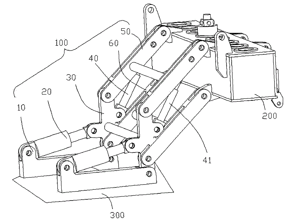
[0023] see figure 1 , In a preferred embodiment of the present invention, a link mechanism 100 is used to connect a powder ridge head 200 and a support table 300, and includes a base 10, a first driving part 20, a swinging member 30, a The second driving part 40 , a master link 50 and a slave link 60 . In this embodiment, several drill pipes (not shown in the figure) are installed on the powder ridge head 200, and the several drill pipes are used for planting various crops in the powder ridge, such as rice, corn, sugarcane, soybean, etc. Land, in this embodiment, the field or land is defined as the working surface of the several drill pipes.

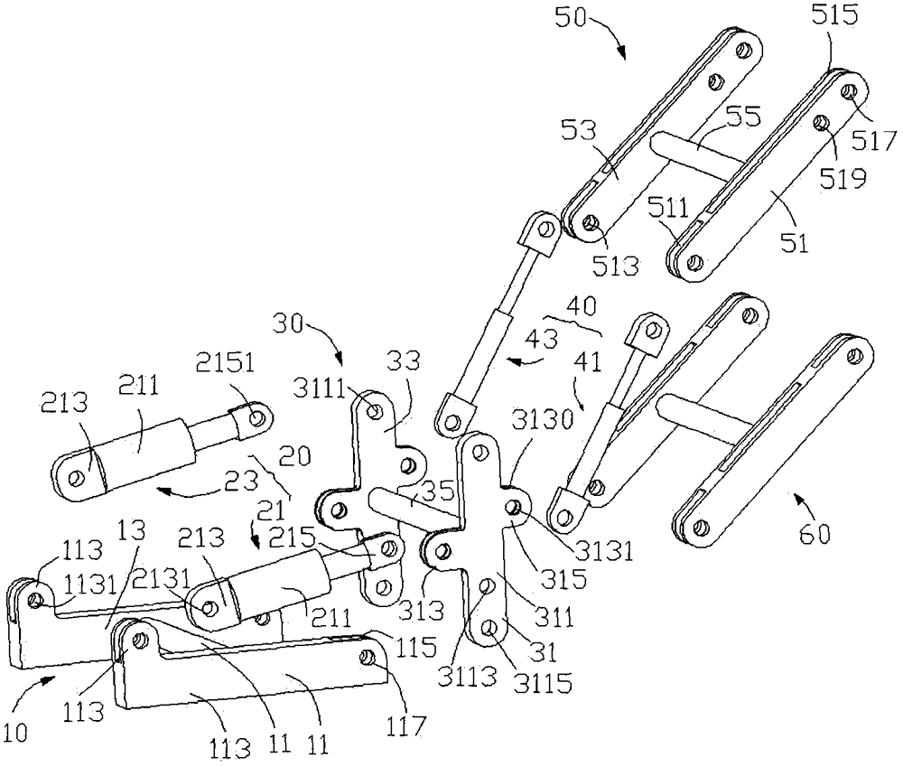
[0024] read on figure 1 and figure 2 , the base 10 is mounted on the supporting platform 300 by common fixing means, such as screws, welding, etc. The base 10 includes a first support block 11 , a second support block 13 and a connecting rod 15 . The connecting rod 15 is substantially vertically connected to the first support block...


PUM


Abstract

The invention discloses a connecting rod mechanism, which is used for connecting a powder ridge head with a drill stem and a support table. The connecting rod mechanism comprises a base, an oscillating element, a main connecting rod and a driven connecting rod, wherein the base is arranged on the support table; the oscillating element is rotationally arranged on the base; one end of the main connecting rod and one end of the driven connecting rod are rotationally connected with the oscillating element respectively; the other ends of the main connecting rod and the driven connecting rod are respectively connected with the powder ridge head; the main connecting rod, the driven connecting rod, the oscillating element and the powder ridge head are arranged on four sides of a first parallelogram, respectively; the main connecting rod can rotate relative to the oscillating element; and the drill stem is moved to a preset position in the direction vertical to the operation plane of the drill stem. The connecting rod mechanism disclosed by the invention is simple in structure; the powder ridge head can rotate to the preset position, so that the drill stem arranged on the powder ridge head can carry out linear movement in the direction vertical to the operation plane of the drill stem and is prevented from being damaged when entering into the earth obliquely.

Description

technical field [0001] The invention relates to an agricultural machine, in particular to a link mechanism of a subsoiler. Background technique [0002] In the past, loose plowing was achieved by hoes or oxen plowing, but no matter which of the above methods is not only laborious, but also inefficient. Therefore, for a large area of ​​land that needs loose plowing, the traditional method can no longer be adapted. Therefore, , there have been many automated tillers. [0003] For example, a high-speed double-screw deep cultivator is disclosed in the patent document whose application number is 201220013529.3 and the application date is 2012.1.13 and the authorized announcement date is 2012.11.21. , the connecting rod mechanism includes two oil cylinders, through the synergistic effect of the two oil cylinders, the auger rod can be used to plow the soil deeply. When the rod mechanism drives the auger rod to enter the soil obliquely, it is easily bent by the radial force, and i...

Claims


Application Information

Patent Timeline
IPC IPC(8): A01B71/06
Inventor 李阳铭
Owner GUANGXI WUFENG MACHINERY CO LTD
Features
  • R&D
  • Intellectual Property
  • Life Sciences
  • Materials
  • Tech Scout
  • Unparalleled Data Quality
  • Higher Quality Content
  • 60% Fewer Hallucinations
Learn More