
Retaining device

A technology of holding device and supporting part, which is applied to positioning device, clamping device, clamping and other directions, can solve the problems of easy occurrence of jitter and insignificant anti-shake effect, and achieve the effect of increasing rigidity and controlling jitter.

Active Publication Date: 2015-04-22
XCMG CONSTR MACHINERY
View PDF7 Cites 0 Cited by
  • Summary
  • Abstract
  • Description
  • Claims
  • Application Information

AI Technical Summary

Problems solved by technology

But the anti-shake effect of the tooling is not obvious
[0007] In short, the unfavorable processing state of the truss arm section of construction machinery that is prone to vibration during the boring process on the double-sided floor boring and milling machine has always troubled the technicians. Although after many years of continuous attempts, there is no relatively successful solution at home and abroad. to solve the technical problem

Method used


Image

  • Retaining device
  • Retaining device
  • Retaining device

Examples


Embodiment Construction

[0051] The following will clearly and completely describe the technical solutions in the embodiments of the present invention with reference to the accompanying drawings in the embodiments of the present invention. Obviously, the described embodiments are only some, not all, embodiments of the present invention. The following description of at least one exemplary embodiment is merely illustrative in nature and in no way taken as limiting the invention, its application or uses. Based on the embodiments of the present invention, all other embodiments obtained by persons of ordinary skill in the art without creative efforts fall within the protection scope of the present invention.

[0052] The relative arrangements of components and steps, numerical expressions and numerical values ​​set forth in these embodiments do not limit the scope of the present invention unless specifically stated otherwise. At the same time, it should be understood that, for the convenience of descriptio...


PUM


Abstract

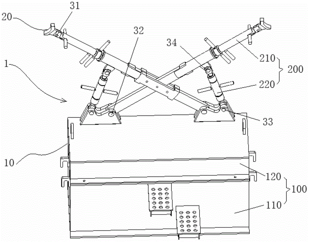
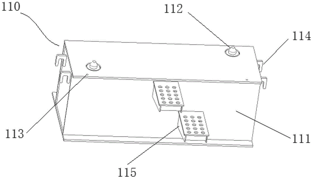
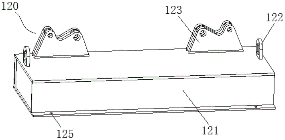
The invention discloses a retaining device. The retaining device is used for preventing an arm section of a truss arm from shaking during a machining process, and comprises a supporting main body and at least one supporting leg group, wherein the supporting main body comprises a basic supporting part and at least one adjusting supporting part which is movably connected on the basic supporting part and corresponds to the at least one supporting leg group one by one, the supporting leg group comprises two supporting legs which are respectively connected on the corresponding adjusting supporting parts, the positions of the supporting legs relative to the basic supporting part can be changed by the adjusting supporting parts, and under the working condition of the retaining device, the two supporting legs are respectively rigidly supported on the supporting main body and symmetrically prop against the arm section of the truss arm. According to the retaining device disclosed by the invention, under the working condition of the retaining device, symmetrical rigid supporting forces are applied to the arm section of the truss arm by the two supporting legs, so that the retaining device can effectively resist an axial cutting component force, or enhance the rigidness of the arm section of the truss arm, thereby effectively controlling the shaking phenomenon of the arm section of the truss arm during the machining process.

Description

technical field [0001] The invention relates to the field of engineering machinery, in particular to a holding device. Background technique [0002] The truss arm is a truss-type large-scale structural member welded by pipes. The construction machinery truss arm is composed of the top section truss arm section, the middle section truss arm section, and the bottom section truss arm section. . [0003] When processing the hinge point holes of each truss arm section, boring is usually carried out on a double-sided floor boring and milling machine (counter boring machine) both at home and abroad. However, the cross-sectional structure and height of the truss jib section determine the instability when boring the hinge point hole, because: [0004] The height of the truss boom section is generally between 1.6 and 2.8 meters, and the width is between 2.0 and 3.2 meters. When machining the boring hole, the machine tool spindle has an axial cutting force on the reaming point hole...

Claims


Application Information

Patent Timeline
Patent Type & Authority Applications(China)
IPC IPC(8): B23Q3/06
CPCB23Q3/062B23Q3/069B23Q2703/10
Inventor 李翔高瑞举宋学楠董志强赵世航孙跃张鹏刘剑锋
Owner XCMG CONSTR MACHINERY
Learn More