Mold for manufacturing fully-blocking bridge concrete compound insulation block

A technology of composite heat preservation and blocking bridge, applied in the direction of molds, manufacturing tools, ceramic molding machines, etc., can solve the problem of strength and thermal bridge structure that cannot be solved, avoid thermal bridge phenomenon, facilitate handling and masonry, The effect of improving thermal insulation performance

Active Publication Date: 2015-04-22
刘立才
View PDF6 Cites 1 Cited by
  • Summary
  • Abstract
  • Description
  • Claims
  • Application Information

AI Technical Summary

Problems solved by technology

[0006] To sum up, neither the traditional cement foam insulation brick nor the improved composite material insulation block can solve the strength problem and thermal bridge structure problem during construction.

Method used


Image

  • Mold for manufacturing fully-blocking bridge concrete compound insulation block
  • Mold for manufacturing fully-blocking bridge concrete compound insulation block
  • Mold for manufacturing fully-blocking bridge concrete compound insulation block

Examples


Embodiment 1

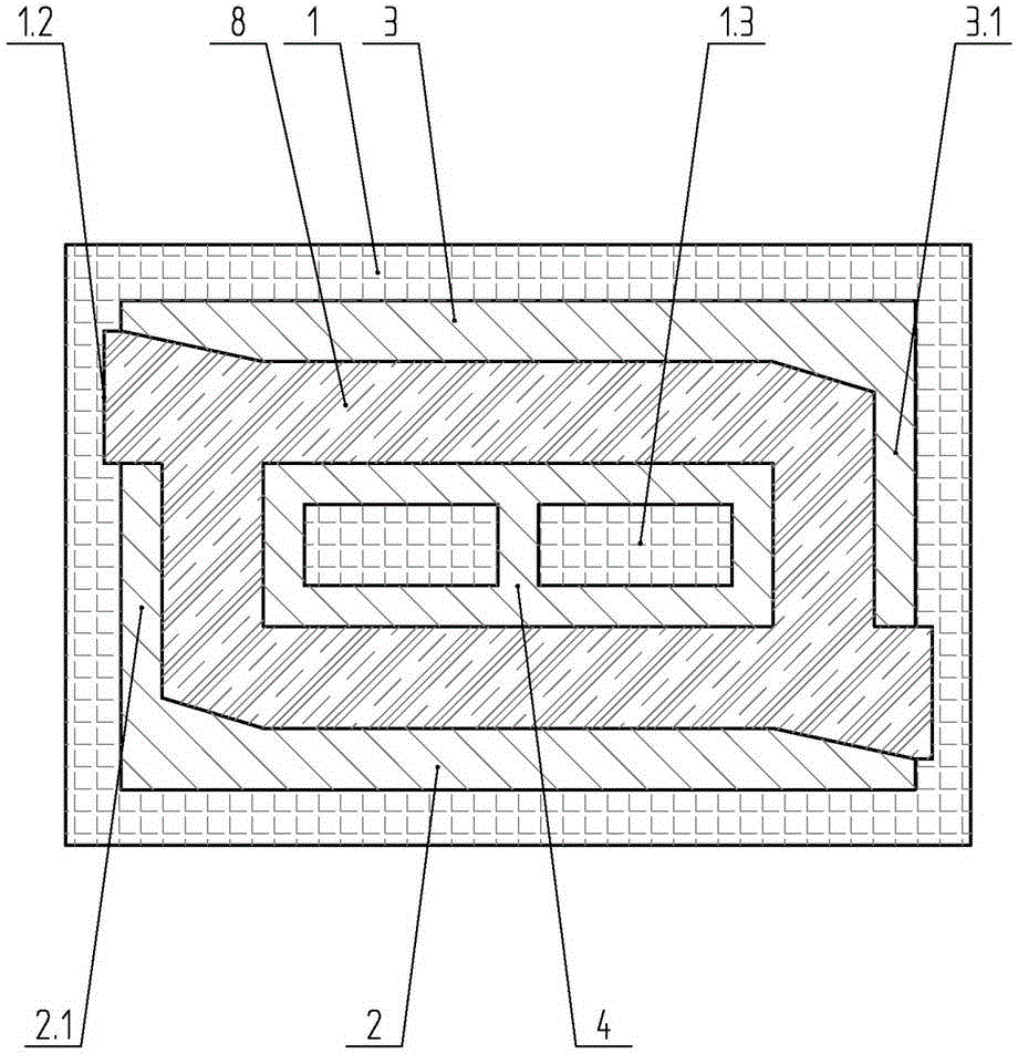
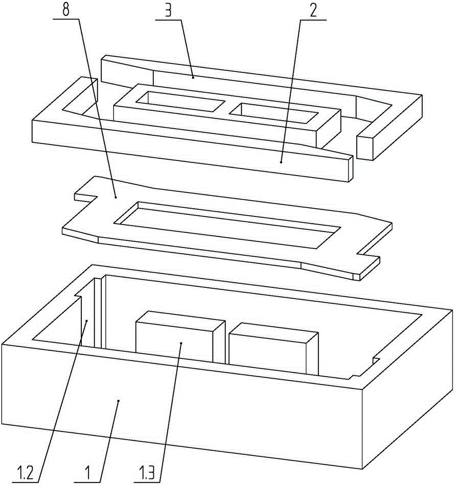
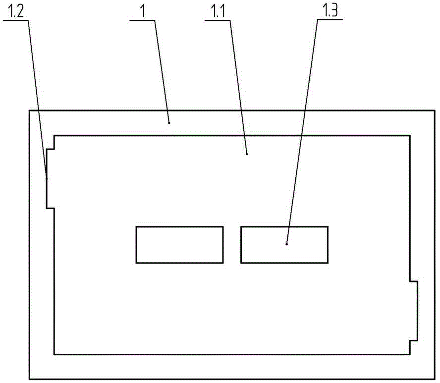
[0047] Such as Figure 1 to 5 As shown, a mold for making a full-blocking bridge concrete composite thermal insulation block includes an outer mold 1, a pressure mold and a mold cover 8. The outer mold 1 has a rectangular cavity passing through the upper and lower sections, and the pressing mold is divided into a first pressing mold 2 and a second pressing mold 3. The first pressing mold 2 and the second pressing mold 3 are arranged oppositely and separated by a reserved cavity 7 into two independent parts. The inner wall of the first die 2 has a first protrusion 2.1 facing inward and in the shape of a straight plate structure. Correspondingly, the inner wall of the second pressing mold 3 has an inwardly directed second protrusion 3.1 with a straight plate structure. The first protrusion 2.1 and the second protrusion 3.1 are both located at the ends of the first stamper 2 and the second stamper 3 and are centrally symmetrically arranged, and are also separated by the reserved...

Embodiment 2

[0059] Such as Figure 7 As shown, the difference from Embodiment 1 is that, in this embodiment, the first protrusion 2.1 and the second protrusion 3.1 are both hollow triangular frame structures, and the third pressing mold 4 is a parallelogram structure. There is also a second columnar body 1.4 in the outer mold 1. The shape of the second columnar body 1.4 matches the inner contours of the first protrusion 2.1 and the second protrusion 3.1, so that it can be inserted into the corresponding first protrusion 2.1 and the second protrusion 2.1. Two bulges in 3.1.

Embodiment 3

[0061] Such as Picture 8 As shown, the difference from Embodiment 1 is that, in this embodiment, the first protrusion 2.1 and the second protrusion 3.1 are both hollow rectangular frame structures, and the third pressing mold 4 has a rectangular structure.


PUM


Abstract

A mold for manufacturing a fully-blocking bridge concrete compound insulation block comprises an outer mold, a pressing mold and a mold cover. The outer mold is provided with a rectangular inner cavity which penetrates through the upper end face and the lower end face of the outer mold, and the opposite inner walls of the rectangular inner cavity are each provided with a first vertical groove. The outer contour of the pressing mold is matched with the contour of the rectangular inner cavity. The outer contour of the mold cover is matched with the inner contour of the pressing mold. The mold has the advantages that the mold has the unique shape, so that it is guaranteed that a concrete shell of the manufactured block is completely partitioned by a polystyrene board and therefore a hot bridge can not be formed; the energy-saving efficiency reaches 75%, the latest national mandatory standard at the present stage is met, the conventional defects that cracks, empty plumps, leakage, disengaging and the like are likely to happen in technology when heat insulation materials are externally attached to and hung to the outer portion of a building body at present are completely overcome, the construction cost is lowered, the process procedures are reduced, the construction period is shortened, and the worries to the heating and refrigerating cost, which is continuously increased, of owners in later period are relieved.

Description

Technical field [0001] The invention belongs to the field of building materials, and specifically relates to a block mold. Background technique [0002] In the construction market so far, it can be said that the recognized and mature self-insulation integrated filling material has been a blank. Although cement foam insulation boards, infinite foam insulation boards, aerated and sand-filled concrete blocks, small concrete hollow bricks and other frame structure filling materials are widely used in the market and have been used for many years, no matter from their own thermal insulation and energy saving effects , Or from its construction process procedures, it is impossible to fundamentally solve the problem of "self-insulation integration" and simplify the process and improve efficiency. Especially with the continuous improvement of the basic standards for energy saving and emission reduction, the energy saving efficiency of building walls has increased to the height of compulso...

Claims


Application Information

Patent Timeline
Patent Type & Authority Applications(China)
IPC IPC(8): B28B7/00
CPCB28B7/162
Inventor 刘立才
Owner 刘立才
Why Eureka
Try Eureka