A mold for making concrete composite thermal insulation blocks of fully blocked bridges
A technology of composite heat preservation and blocking bridge, applied in the direction of molds, manufacturing tools, ceramic molding machines, etc., can solve the problems of failure to solve the strength problem and thermal bridge structure, etc., to avoid thermal bridge phenomenon, high connection strength, wide application Foreground effect
- Summary
- Abstract
- Description
- Claims
- Application Information
AI Technical Summary
Problems solved by technology
Method used
Image
Examples
Embodiment 1
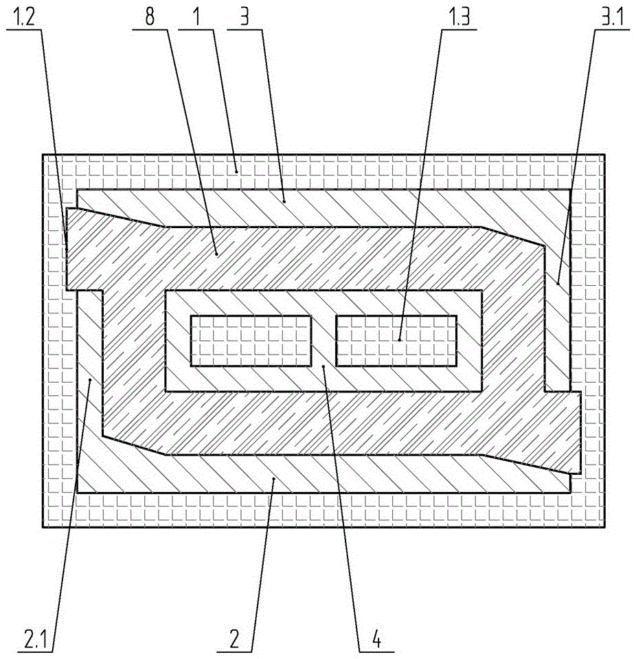
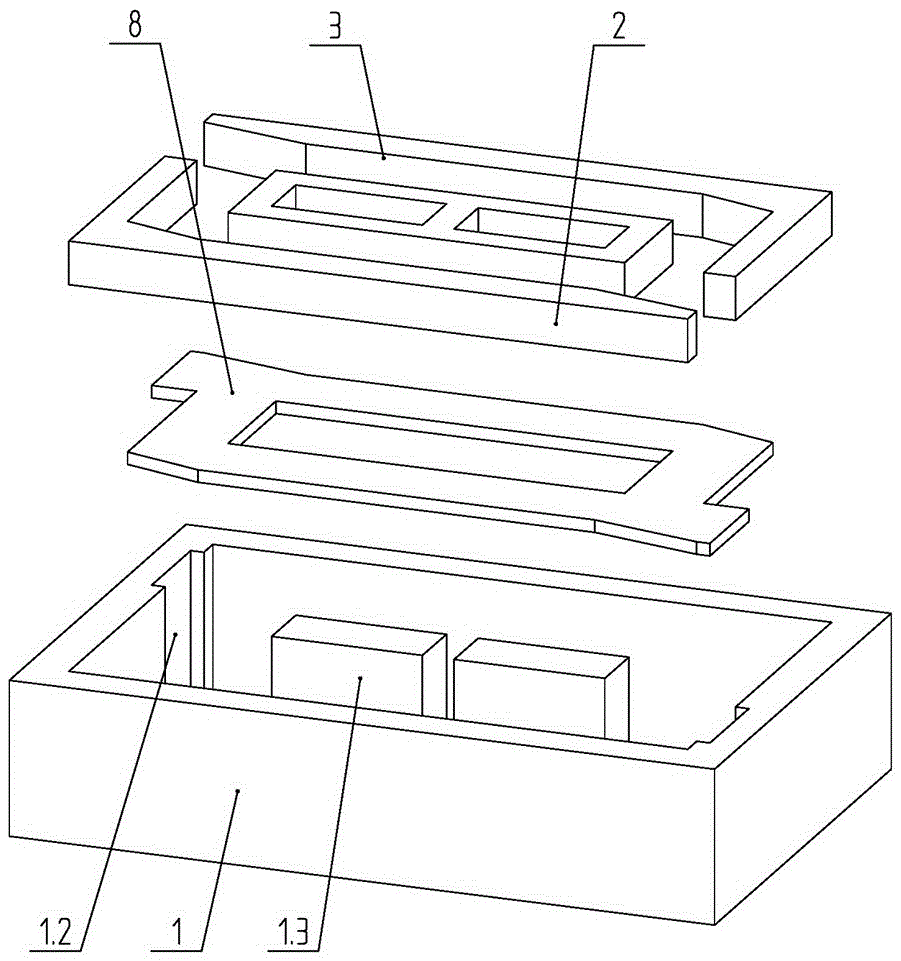
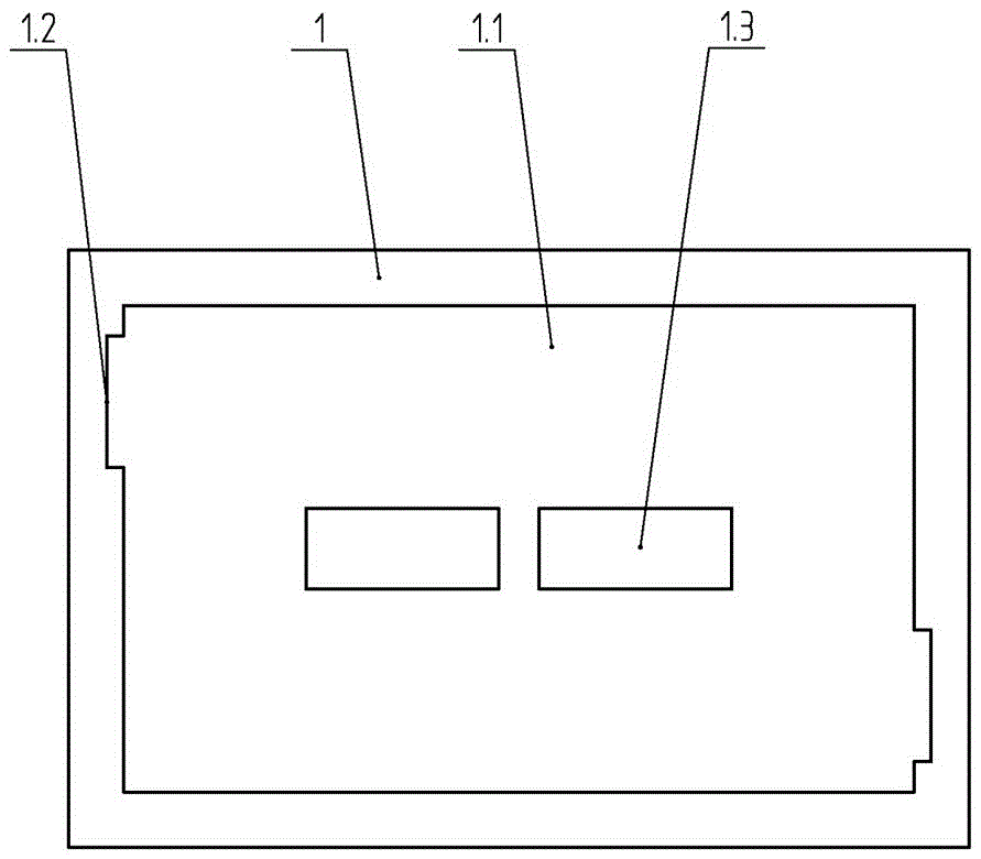
[0047] Such as Figures 1 to 5As shown, a mold for making a concrete composite thermal insulation block for a fully blocked bridge includes an outer mold 1 , a compression mold and a mold cover 8 . The outer die 1 has a rectangular cavity through the upper and lower sections, and the die is divided into a first die 2 and a second die 3 . The first die 2 and the second die 3 are oppositely arranged, and both are separated into two independent parts by the reserved cavity 7 . The inner wall of the first die 2 has a first protrusion 2.1 facing inward and shaped as a straight plate structure. Correspondingly, the inner wall of the second die 3 has a second protrusion 3.1 facing inward and shaped like a straight plate. Both the first protrusion 2.1 and the second protrusion 3.1 are located at the ends of the first die 2 and the second die 3 and arranged symmetrically about the center, and are also separated by the reserved cavity 7 . A first groove 1.2 is provided on two opposit...
Embodiment 2
[0059] Such as Figure 7 As shown, the difference from Embodiment 1 is that in this embodiment, the first protrusion 2.1 and the second protrusion 3.1 are hollow triangular frame structures, and the third die 4 is a parallelogram structure. There is also a second columnar body 1.4 in the outer mold 1, and the shape of the second columnar body 1.4 matches the inner contours of the first protrusion 2.1 and the second protrusion 3.1, so that it can be inserted into the corresponding first protrusion 2.1 and the second protrusion 3.1. II Bump 3.1.
Embodiment 3
[0061] Such as Figure 8 As shown, the difference from Embodiment 1 is that in this embodiment, the first protrusion 2.1 and the second protrusion 3.1 are both hollow rectangular frame structures, and the third die 4 is a rectangular structure.
PUM
 Abstract
Description
Claims
Application Information
 - R&D
- Intellectual Property
- Life Sciences
- Materials
- Tech Scout
- Unparalleled Data Quality
- Higher Quality Content
- 60% Fewer Hallucinations
Browse by: Latest US Patents, China's latest patents, Technical Efficacy Thesaurus, Application Domain, Technology Topic, Popular Technical Reports.
© 2025 PatSnap. All rights reserved.Legal|Privacy policy|Modern Slavery Act Transparency Statement|Sitemap|About US| Contact US: help@patsnap.com


