Crane counterweight hoisting system

A counterweight lifting and crane technology, which is applied in the direction of cranes, mechanical equipment, fluid pressure actuators, etc., can solve the problems of inability to synchronize counterweight cylinders, etc., and achieve the effect of simple structure and convenient operation

Active Publication Date: 2015-04-22
ZOOMLION HEAVY IND CO LTD
View PDF9 Cites 5 Cited by
  • Summary
  • Abstract
  • Description
  • Claims
  • Application Information

AI Technical Summary

Problems solved by technology

[0010] The main purpose of the present invention is to provide a crane counterweight lifting system to solve the problem that the counterweight lifting system of the crane in the prior art cannot make its counterweight cylinders act synchronously reliably

Method used


Image

  • Crane counterweight hoisting system
  • Crane counterweight hoisting system
  • Crane counterweight hoisting system

Examples


Embodiment Construction

[0031] It should be noted that, in the case of no conflict, the embodiments in the present application and the features in the embodiments can be combined with each other. The present invention will be described in detail below with reference to the accompanying drawings and examples.

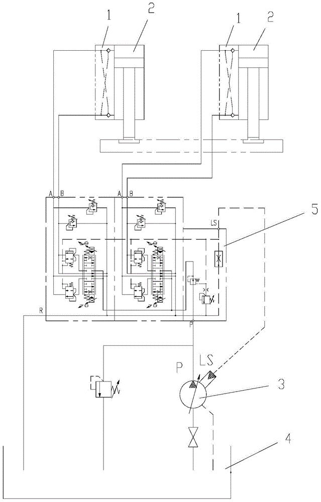
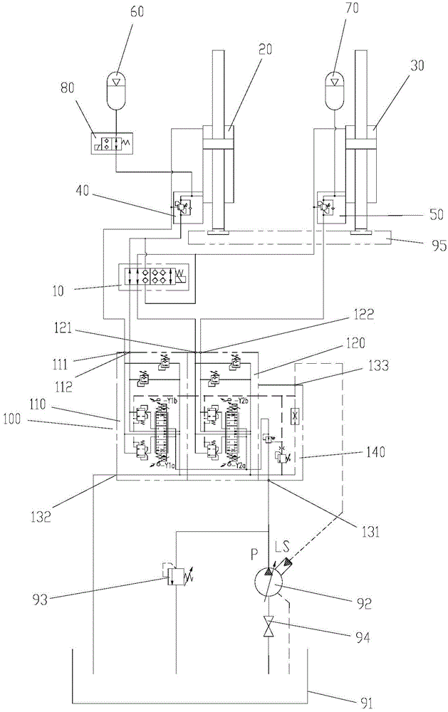
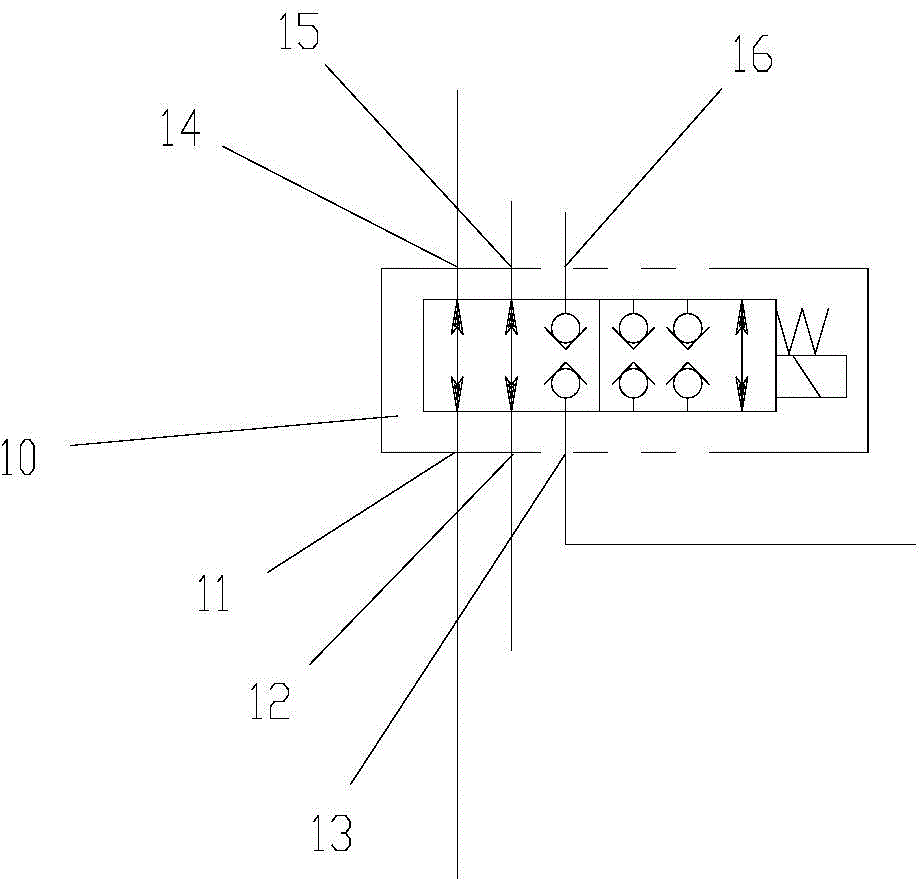
[0032] The present invention provides a crane counterweight lifting system, please refer to Figure 2 to Figure 5, the crane counterweight lifting system includes a main control valve group 100, a first oil cylinder 20 and a second oil cylinder 30, the main control valve group 100 includes a first control valve group 110 and a second control valve group 120, the first control valve group 110 It is controlled and connected with the first oil cylinder 20, and the second control valve group 120 is controlled and connected with the second oil cylinder 30. Both the first oil cylinder 20 and the second oil cylinder 30 are double-acting oil cylinders. The crane counterweight lifting system also includ...


PUM


Abstract

The invention provides a crane counterweight hoisting system. A first control valve bank and a first oil cylinder are in pilot connection. A second control valve bank and a second oil cylinder are in pilot connection. The first oil cylinder and the second oil cylinder are both double-acting oil cylinders. The crane counterweight hoisting system also comprises a synchronous selection control valve which is arranged between a main control valve bank and the first and second oil cylinders and contains a first working state and a second working state. In the first working state of the synchronous selection control valve, the first oil cylinder is separately controlled by the first control valve bank, and the second oil cylinder is separately controlled by the second control valve bank. In the second working state of the synchronous selection control valve, a lower rod port of the first oil cylinder is connected with an upper rod port of the second oil cylinder through the synchronous selection control valve so as to connect the first oil cylinder and the second oil cylinder in series. Thus, synchronization action of the first and second oil cylinders is realized. According to the invention, the problem that synchronization action of counterweight oil cylinders cannot be reliably realized by a crane counterweight hoisting system is solved.

Description

technical field [0001] The invention relates to the field of hydraulic control, in particular to a crane counterweight lifting system. Background technique [0002] Such as figure 1 As shown, the existing crane counterweight lifting hydraulic system consists of a hydraulic lock 1, a counterweight lifting cylinder 2, a variable displacement pump 3, a hydraulic oil tank 4 and a proportional valve 5. [0003] After the pressure oil comes out from the variable displacement pump 3, it is independently distributed through the two valves of the proportional valve 5, and enters the left counterweight lifting cylinder and the right counterweight lifting cylinder respectively. By independently controlling the valve openings of the two valves, the movement speed of the left and right counterweight oil cylinders is controlled to achieve the purpose of synchronizing the speed of the left and right counterweight lifting cylinders. [0004] After the left and right counterweight oil cyli...

Claims


Application Information

Patent Timeline
Patent Type & Authority Applications(China)
IPC IPC(8): B66C23/72
CPCB66C23/72F15B1/02F15B11/22F15B13/0807
Inventor 杨翔罗贤智刘伟黄杰
Owner ZOOMLION HEAVY IND CO LTD
Why Eureka
Try Eureka