Steam exhaust diffusion flow guiding structure of steam turbine and steam turbine

A steam turbine and steam exhaust technology, which is applied in the direction of machines/engines, mechanical equipment, engine components, etc., can solve the risk of increasing steam leakage, complicated installation and maintenance of low-pressure outer cylinders, and the inability of the upper half of low-pressure outer cylinders to fall into place as a whole and other problems to achieve the effect of avoiding the decline of aerodynamic performance, improving aerodynamic performance, and good aerodynamic performance

Active Publication Date: 2015-04-22
DONGFANG TURBINE CO LTD
View PDF7 Cites 1 Cited by
  • Summary
  • Abstract
  • Description
  • Claims
  • Application Information

AI Technical Summary

Problems solved by technology

During on-site installation, after the lower half of the low-pressure outer cylinder is installed, install the low-pressure inner cylinder 4 and the exhaust guide ring, and then hoist the upper half of the low-pressure outer cylinder 2 after completion. At this time, due to the existence of the exhaust guide ring 1 And the exhaust cone 3 is fixed on the upper half 2 of the low-pressure outer cylinder. When the exhaust cone 3 falls along the radial direction of the exhaust guide ring 1 (usually, it is easier to construct when falling along the sky and the ground), because it extends into the exhaust The part 31 of the guide ring is blocked by the upper half ring of the exhaust guide ring 1, which is located at the predetermined drop path of the exhaust cone 3, which interferes with the corresponding part 31 of the exhaust cone 3, so that the low pressure The upper half 2 of the outer cylinder cannot be lowered into place as a whole
When overhauling, first disassemble and lift the upper half 2 of the low-pressure outer cylinder. Since the exhaust cone 3 fixed on the upper half 2 of the low-pressure outer cylinder is lifted upward along the radial direction of the exhaust guide ring 1, usually, along the direction of the sky and the earth Being hoisted is more convenient for construction, because the part 31 extending into the exhaust guide ring 1 is blocked by the upper half ring of the exhaust guide ring 1, which is located at the predetermined ascending path of the exhaust cone 3. The corresponding part 31 of the exhaust cone 3 interferes, so that the upper half 2 of the low-pressure outer cylinder cannot be hoisted as a whole
[0004] Therefore, in the design of the exhaust steam diffuser guide structure of the steam turbine, it should be considered how to at least overcome the exhaust steam guide ring when the upper half 2 of the low-pressure outer cylinder is integrally hoisted (lifted) and moves along the radial direction of the exhaust steam guide ring 1 Interference with the corresponding part 31 of the exhaust cone 3, so that the upper half 2 of the low-pressure outer cylinder cannot be hoisted (lifted) as a whole
In an existing design scheme, the upper half 2 of the low-pressure outer cylinder is divided into left and right parts, and then separately hoisted (lifted). Although the split design structure of the upper half 2 of the low-pressure outer cylinder solves the problem of exhaust steam diversion The problem that the ring 1 interferes with the corresponding exhaust cone 3, but it is the split structure of the upper half 2 of the low-pressure outer cylinder that makes the installation and maintenance of the low-pressure outer cylinder very complicated, and also adds a large vertical seal On the other hand, the risk of steam leakage is increased, and the split structure design scheme of the upper half of the low-pressure outer cylinder 2 is not ideal

Method used


Image

  • Steam exhaust diffusion flow guiding structure of steam turbine and steam turbine
  • Steam exhaust diffusion flow guiding structure of steam turbine and steam turbine
  • Steam exhaust diffusion flow guiding structure of steam turbine and steam turbine

Examples


Embodiment Construction

[0031] In order to describe the technical features and effects of the present invention in detail, and can be implemented in accordance with the content of this specification, the following further describes the embodiments of the present invention in conjunction with the accompanying drawings.

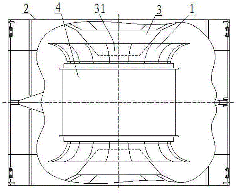
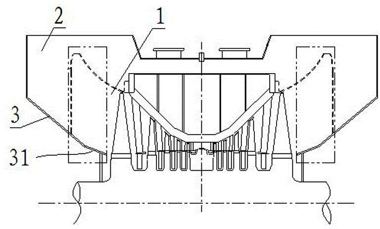
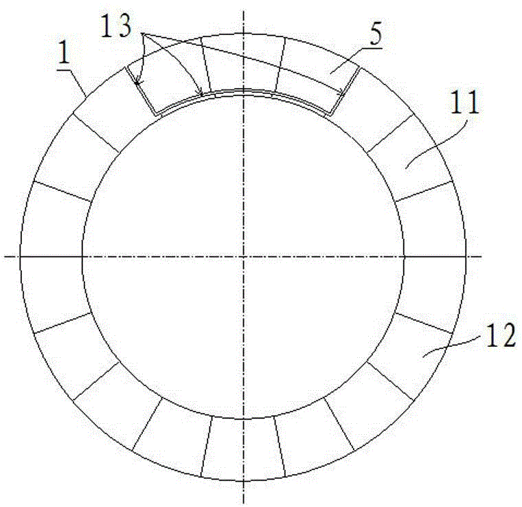
[0032] See image 3 , Image 6 and Figure 7 , Is a steam turbine exhaust steam diffusion and diversion structure of the present invention. The steam turbine includes a low pressure outer cylinder composed of a low pressure outer cylinder upper half 2 and a low pressure outer cylinder lower half. The low pressure outer cylinder upper half 2 has a fixed and integrated exhaust Steam cone 3. See also Figure 4 and Figure 5 , The exhaust steam diffuser and guide structure includes an exhaust steam guide ring 1 arranged in the low-pressure outer cylinder. The exhaust steam guide ring 1 is divided at the horizontal midplane to form upper and lower half rings 11, 12, The upper and lower half r...


PUM


Abstract

Disclosed is a steam exhaust diffusion flow guiding structure of a steam turbine. The steam turbine comprises a low-pressure outer cylinder composed of a low-pressure outer cylinder upper half portion and a low-pressure outer cylinder lower half portion. The steam exhaust diffusion flow guiding structure comprises a steam exhaust flow guiding ring arranged in the low-pressure outer cylinder. The steam exhaust flow guiding ring comprises an upper half ring, wherein the steam exhaust end surface of the upper half ring is provided with a notch, and a portion, at least obstructed by the steam exhaust flow guiding ring, of a steam exhaust cone body of the low-pressure outer cylinder upper half portion can penetrate through the notch in the radial direction of the upper half ring. According to the invention, the low-pressure outer cylinder upper half portion can integrally descend in place or can be integrally hoisted, and integrality of the low-pressure outer cylinder upper half portion can be kept; the disassembly and assembly process of the low-pressure outer cylinder is simplified, perpendicular sealing surfaces resulting from split structures are omitted, and good steam tightness is ensured; and the problems that in the prior art, due to the fact that a low-pressure outer cylinder upper half portion is divided into a left portion and a right portion, installation, overhauling and maintenance of the low-pressure outer cylinder upper half portion are quite complex, steam tightness is poor, and the low-pressure outer cylinder upper half portion cannot integrally descend in place or cannot be integrally hoisted are solved. The invention further provides the steam turbine.

Description

Technical field [0001] The invention relates to a steam turbine and its exhaust steam diffusing guide device, in particular to a steam turbine exhaust steam diffusing guide structure and a steam turbine. Background technique [0002] See figure 1 and figure 2 The low-pressure outer cylinder is the largest part of the steam turbine body. It is divided into the upper half 2 of the low-pressure outer cylinder and the lower half of the low-pressure outer cylinder at the horizontal midplane. The upper and lower halves are fixed together by flange bolts. The low-pressure inner cylinder is supported and fixed on the turbine base by a support that passes through the lower half of the low-pressure outer cylinder. The end of the low-pressure inner cylinder 4 is fixed with an exhaust steam guide ring 1, which is connected to the low-pressure outer cylinder. The inner wall of the tapered end of the unit is combined to form an exhaust steam diffusion channel for exhausting steam to the conde...

Claims


Application Information

Patent Timeline
Patent Type & Authority Applications(China)
IPC IPC(8): F01D25/30
Inventor 高宏喜李继朝邓凌宇卢平廖兴宝代文花李进王涛周华段增辉
Owner DONGFANG TURBINE CO LTD
Why Eureka
Try Eureka