Fan assembly and nozzle used for same

A technology of fan components and nozzles, applied in jet pumps, liquid volumetric machinery, pump devices, etc., can solve problems such as wear, nozzles that cannot provide sufficient friction, and loose sliding connections

Inactive Publication Date: 2015-04-22
任文华
View PDF1 Cites 0 Cited by
  • Summary
  • Abstract
  • Description
  • Claims
  • Application Information

AI Technical Summary

Problems solved by technology

Because the relative sliding between the main body and the inlet part of the nozzle of this fan will cause wear and tear, the sliding connection between the main body and the inlet part will become very loose after long-term use, and it cannot provide enough friction to stabilize the main body of the nozzle. in a certain set position, such as stably in a certain inclined position

Method used


Image

  • Fan assembly and nozzle used for same
  • Fan assembly and nozzle used for same
  • Fan assembly and nozzle used for same

Examples


Embodiment Construction

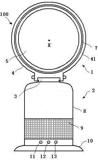
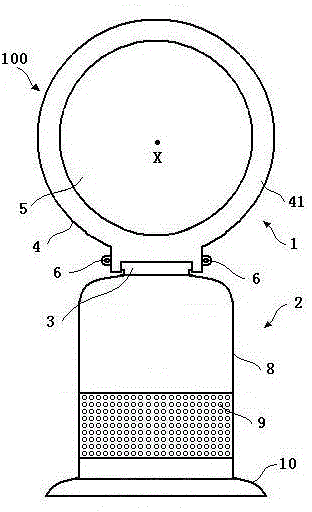
[0044] Figure 1 is a schematic view of the fan assembly of the present invention viewed from the front of the device, figure 2 and image 3 Respectively are the rear view and the side view of the fan shown in Fig. l. From Figure 1 to Figure 3 It can be seen from the figure that the fan 100 includes a base 2 , a nozzle 1 and an adjustment mechanism 6 located on the base 2 . The base 2 includes a lower base 10 and an upper base 8 positioned on the lower base 10. The upper base 8 includes an air inlet 9 and a plurality of buttons 11, 12 and 13 operable by the user. The air inlet 9 is formed on the upper base. in the form of a plurality of holes in the seat housing. Air outside the fan is sucked into the upper base 8 through the air inlet 9 .

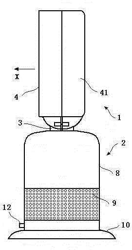
[0045] Figure 4 is a schematic diagram of the nozzle of the fan shown in Figure 1, Figure 5 and Figure 6 They are the side view and exploded view of the nozzle of the fan shown in Fig. l respectively. From Figure 4 to Figure 6...


PUM


Abstract

A fan assembly comprises a base and a nozzle. The nozzle comprises a nozzle body, a basic part and adjusting mechanisms. The nozzle body is connected with the basic part in a sliding part, the adjusting mechanisms are used for adjusting the tightening degree of the sliding connection position of the nozzle body and the basic part, and the nozzle body can slide to an inclined position from a non-inclined position relative to the basic part, and comprises a first shell, a first internal channel, a first air inlet and a first air outlet, wherein the nozzle body limits a through hole. The basic part comprises a second shell, a second internal channel, a second air inlet and a second air outlet. The first internal channel is communicated with the second internal channel, and when the nozzle body slides to the inclined position from the non-inclined position relative to the basic part, the orientation of the first air inlet changes. The invention further provides the nozzle used for the fan assembly.

Description

technical field [0001] The invention relates to a fan assembly and a nozzle used for the fan assembly. Background technique [0002] A conventional fan generally includes a set of blades rotating around a shaft and a motor for driving the rotation of the set of blades to generate air flow. The set of blades is typically located within a cage that allows airflow to pass through while preventing human access to the set of rotating blades. [0003] Such fans can be of various sizes and shapes. For example, ceiling fans may have a diameter of at least 1000 millimeters and are typically mounted in a suspended fashion from the ceiling to provide downward airflow. As another example, desk fans typically have a diameter of 300 millimeters and are typically free standing and easy to move. Other types of fans can be placed on the floor or mounted on a wall. [0004] The disadvantage of this type of fan is that the airflow produced by the rotating blades is usually uneven or "surge...

Claims


Application Information

Patent Timeline
Patent Type & Authority Applications(China)
IPC IPC(8): F04F5/16F04F5/44F04F5/48F04B41/06
CPCF04F5/16F04B41/06F04F5/461
Inventor 任文华
Owner 任文华
Why Eureka
Try Eureka