
Direct-current switch

A technology of DC switches and current sensors, which is applied in the direction of measuring current/voltage, measuring devices, instruments, etc. It can solve the problem that DC switches cannot monitor current and voltage in real time, and achieve the effect of reducing arcing and improving safety

Inactive Publication Date: 2015-04-22
XUJI GRP +3
View PDF7 Cites 1 Cited by
  • Summary
  • Abstract
  • Description
  • Claims
  • Application Information

AI Technical Summary

Problems solved by technology

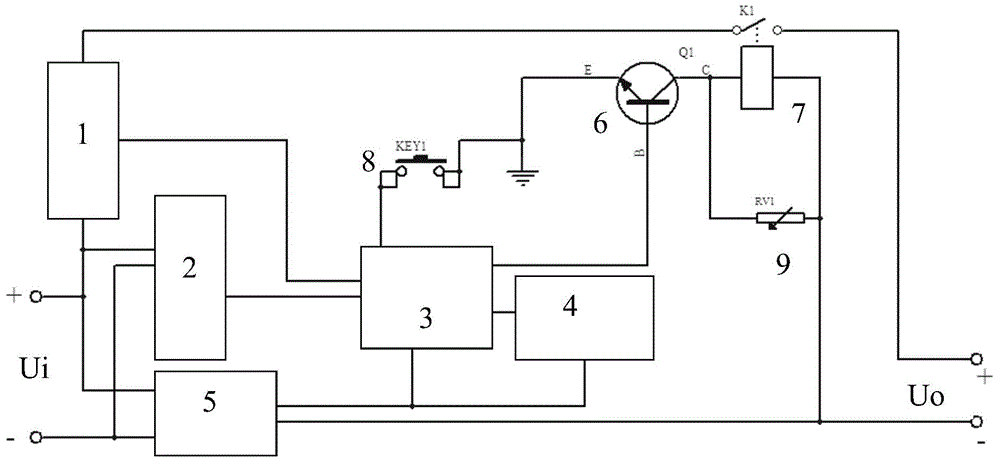
[0003] The purpose of the present invention is to provide a DC switch to solve the problem that the existing DC switch cannot monitor its current and voltage in real time

Method used


Image

  • Direct-current switch

Examples


Embodiment Construction

[0014] The present invention will be described in further detail below in conjunction with the accompanying drawings.

[0015] A DC switch, including a relay, the DC switch also includes a relay control module, the relay control module includes an MCU, the MCU controls the coil connected to the relay, the MCU samples and connects a current sensor and a voltage sensor, the input interface of the DC switch The contacts of the relay are connected in series on the line between the output interface and the current sensor, the current sensor is used to measure the current flowing through the relay contact circuit, and the voltage sensor is used to measure the input voltage of the DC switch.

[0016] Based on the above technical solutions and in conjunction with the accompanying drawings, the following specific implementation is given.

[0017] The invention provides a DC switch, which realizes the integrated realization of the control and measurement of the DC switch, and enables ac...


PUM


Abstract

The invention relates to a direct-current switch comprising a relay and a relay control module. The relay control module comprises an MCU which is in control connection with a coil of the relay and is sampling connection with a current sensor and a voltage sensor. The current sensor is used for measuring the current flowing through a contact loop of the relay, and the voltage sensor is used for measuring the input voltage of the direct-current switch. The current state and voltage state of the direct-current switch can be visually monitored in real time, so that the operating state of the direct-current switch can be known visually, and furthermore, the power consumption can be calculated based on the voltage and current values.

Description

technical field [0001] The invention relates to a direct current switch and belongs to the field of direct current switches. Background technique [0002] Recently, due to the rise of new energy sources, low-voltage DC power consumption has been put on the agenda. Research and development of low-voltage DC equipment has also increased. The application number is 200920205110.6, and the utility model name is "A Mechatronic DC Switch", which discloses a mechatronic DC switch. In this patent, the DC unit, the MCU control unit, and the button unit are connected in sequence, and the DC The unit is connected to the positive and negative input connectors and negative output connectors, the main switch unit is connected in parallel to the isolation arc extinguishing unit, and its input terminals are respectively connected to the positive input connectors and the DC unit, and the output terminals are connected to the positive output connectors. The MCU control unit is connected to th...

Claims


Application Information

Patent Timeline
Patent Type & Authority Applications(China)
IPC IPC(8): H01H47/22G01R19/00G01R22/06
CPCH01H47/22G01R22/06
Inventor 张保增周亚楠冯二浩刘金权侯安家李金龙李贞城罗学宇任慧超
Owner XUJI GRP
Learn More