An electrical device and electric device therewith

A technology of electric equipment and electrical components, which is applied in the direction of electrical components, electrical component structure associations, transformer/inductor parts, etc., can solve problems such as inability to limit the on-current, and achieve the effect of improving electromagnetic compatibility

Active Publication Date: 2014-12-24
ROBERT BOSCH GMBH
View PDF3 Cites 0 Cited by
  • Summary
  • Abstract
  • Description
  • Claims
  • Application Information

AI Technical Summary

Problems solved by technology

However, the inrush current cannot be limited by means of electrical components

Method used


Image

  • An electrical device and electric device therewith
  • An electrical device and electric device therewith
  • An electrical device and electric device therewith

Examples


Embodiment Construction

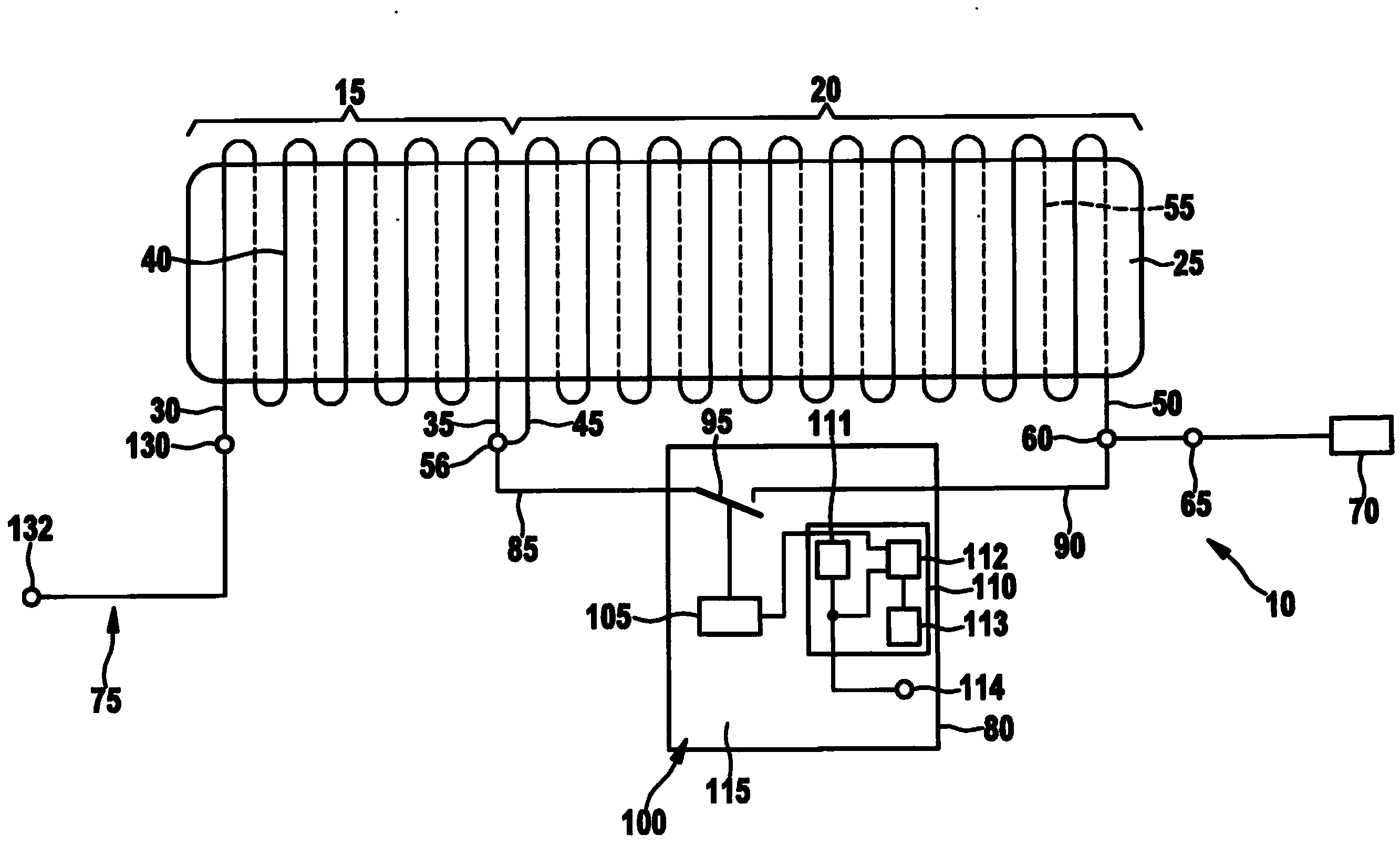
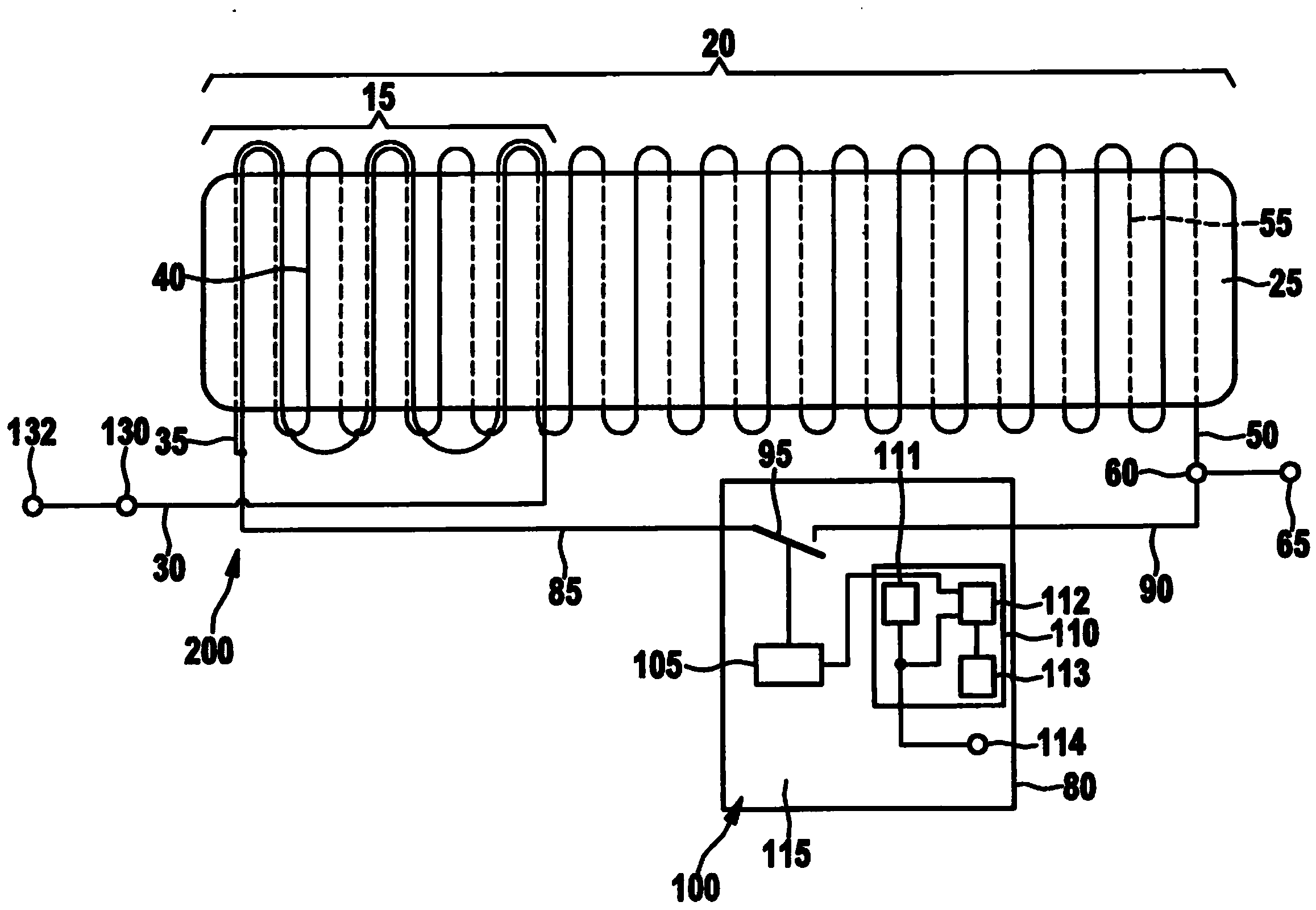
[0022] figure 1 A schematic circuit arrangement of the electrical component 10 according to the first embodiment is shown. The electrical component 10 comprises a first coil 15 and a second coil 20 which are wound around a common coil core 25 . The coil core 25 is ferromagnetic and has ferrite as raw material. Additionally or alternatively, it is conceivable for the coil core 25 to comprise neodymium as material. At the same time, other ferromagnetic materials can be considered for the coil core. In this embodiment, the coil core is designed as a rod core. Alternatively, it is also conceivable for the coil core to be configured as a C core, U core, E core, ER core, EFD core, ring core, EP core or RM core. Alternatively, it is also conceivable to omit the coil core 25 .

[0023] The first coil 15 is arranged directly adjacent to the second coil 20 on a coil core 25 . The first coil 15 has a first input 30 and a first output 35 . The first coil 15 includes a plurality of ...


PUM


Abstract

The invention relates to an electrical component and an electrical device therewith, wherein the electrical component includes a first coil 15, a second coil 20 and a switch element 80 includes, with the first coil 15 has a first input 30 and a first output 35, wherein the second coil 20 has a second input 45 and a second output 50, wherein the first input 30 to an electric power source is connectable, the second output 50 is connected to a consumer 70, wherein the second input 45 and second outputs 50 are connected one another via the switching element 80, wherein the first output 35 is connected to the second input 45, the first coil 15 is formed; increasing an electromagnetic tolerance of the load 70 and the second coil 20 is formed to limit a current to the load 70, the switching element 80 is formed, in the closed position substantially completely bridge the second coil 20 and in the open state a substantially to ensure full flow of electric current through the second coil 20.

Description

technical field [0001] The invention relates to an electrical component and an electromotive device having such an electrical component, wherein the electrical component comprises a first coil, a second coil and a switching element, wherein the first coil has a first input and a first output , wherein the second coil has a second input terminal and a second output terminal, wherein the first input terminal can be connected to an electric energy source, wherein the second output terminal can be connected to an electrical appliance, wherein the second input terminal is connected to the first The two output terminals are connected to each other through a switching element, wherein the first output terminal is connected to the second input terminal, wherein the first coil is configured to improve the electromagnetic compatibility of the consumer, and the second coil is configured to limit the electromagnetic compatibility to the consumer. current flow, wherein the switching elemen...

Claims


Application Information

Patent Timeline
Patent Type & Authority Applications(China)
IPC IPC(8): H01F29/02H01F27/40H01F27/30
CPCH01F29/02H01F27/402
Inventor D·龙巴赫K·登格勒B·克勒
Owner ROBERT BOSCH GMBH
Why Eureka
Try Eureka