led lights

A technology of LED lights and LED lighting, which is applied in lighting and heating equipment, semiconductor devices of light-emitting elements, point light sources, etc., can solve the problems of thermal coupling deterioration and damage to service life, and achieve low heat load, good heat transfer, high efficiency effect

Active Publication Date: 2016-03-16
LEDVANCE GMBH
View PDF4 Cites 0 Cited by
  • Summary
  • Abstract
  • Description
  • Claims
  • Application Information

AI Technical Summary

Problems solved by technology

The part of the LED module for fluorescent lamp retrofits that is intended to be energized should be designed insulated as a contact protection, but the insulation can impair the thermal coupling of the LED to the surrounding environment, which at the same time impairs the service life

Method used


Image

  • led lights
  • led lights
  • led lights

Examples


Embodiment Construction

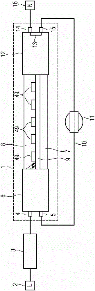
[0041] figure 1 An embodiment of an LED lamp (light-emitting diode lamp) 1 according to the invention is shown, which is suitable without retrofitting measures as a replacement for conventional fluorescent lamps and which can be installed in a lamp originally designed to accommodate e.g. L36W fluorescent lamps in conventional contact devices or sockets for fluorescent lamps or in lighting equipment. Therefore, the LED lamp 1 in this embodiment is a retrofit LED lamp, for example an L36W retrofit LED lamp.

[0042] A series circuit consisting of a choke coil 3 , which may also be bridged or removed, and the LED lamp 1 is connected between the two power supply terminals 2 , 16 , which can be connected to the public mains. The LED lamp 1 has contacts or sockets 4 , 5 , 14 , 15 which correspond to conventional arrangements and configurations of the contacts or sockets of the fluorescent lamps to be replaced. The contact 4 is connected to the inductor 3 , while the contact 14 is ...


PUM


Abstract

The invention relates to an LED lamp (1) having a converter (6) and means connected to the converter of light-emitting diodes (8, 49) arranged on at least one printed circuit board (9) . The transducer is arranged in a multi-piece lockable housing (20) made of non-conductive material that completely surrounds the transducer.

Description

technical field [0001] The invention is based on an LED lamp. Furthermore, the invention relates to a lighting device equipped with such an LED lamp. Background technique [0002] Reference GB2465966A discloses a tubular LED lamp (LED, light emitting diode or device, a diode or device that emits light, also known as a light emitting diode), which can be incorporated into a fluorescent lamp contact or lamp of a lighting device as a substitute for a fluorescent lamp seat. The LED lamp has a transparent tube in which the linear LED arrangement is accommodated. Although this design provides good protection against undesired contact with parts of the LED arrangement used for current supply, it entails a poor thermal coupling of the LED to the surrounding environment, so that the cooling of the LED is compromised. This poor thermal coupling can lead to elevated operating temperatures, which in turn leads to lower light efficiency and shortened lifetime of the LED. In general, ...

Claims


Application Information

Patent Timeline
Patent Type & Authority Patents(China)
IPC IPC(8): F21V23/02F21K99/00F21Y101/02
CPCF21V19/004F21V23/026F21K9/23F21K9/27F21Y2115/10F21V29/713H05B45/44
Inventor 彼得·赫梅尔斯特凡·曼哈特
Owner LEDVANCE GMBH
Why Eureka
Try Eureka