
Integrated Dual Polarized Ceiling Antenna

A ceiling-mounted antenna and dual-polarization technology, which is applied in antenna unit combinations with different polarization directions, antenna coupling, etc., can solve problems such as deformity and horizontal polarization bandwidth cannot be satisfied, and achieve the effect of increasing bandwidth and improving application effect

Active Publication Date: 2018-09-25
GUANGDONG MIKWAVE COMM TECH
View PDF8 Cites 0 Cited by
  • Summary
  • Abstract
  • Description
  • Claims
  • Application Information

AI Technical Summary

Problems solved by technology

[0003] However, the patents retrieved above also have deficiencies, and the horizontal polarization bandwidth cannot meet the bandwidth required by the current 3G (1G)
In addition, the horizontal polarization of Jingxin mode and Catherine mode are both side-fed, which restricts the vertical polarization out-of-roundness, and the vertical polarization roundness is deformed at some frequency points

Method used


Image

  • Integrated Dual Polarized Ceiling Antenna
  • Integrated Dual Polarized Ceiling Antenna
  • Integrated Dual Polarized Ceiling Antenna

Examples


Embodiment 1

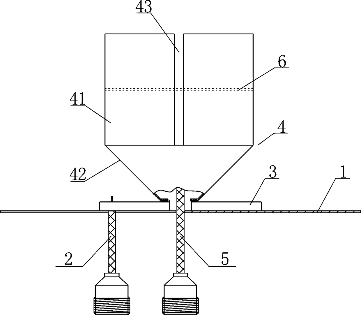
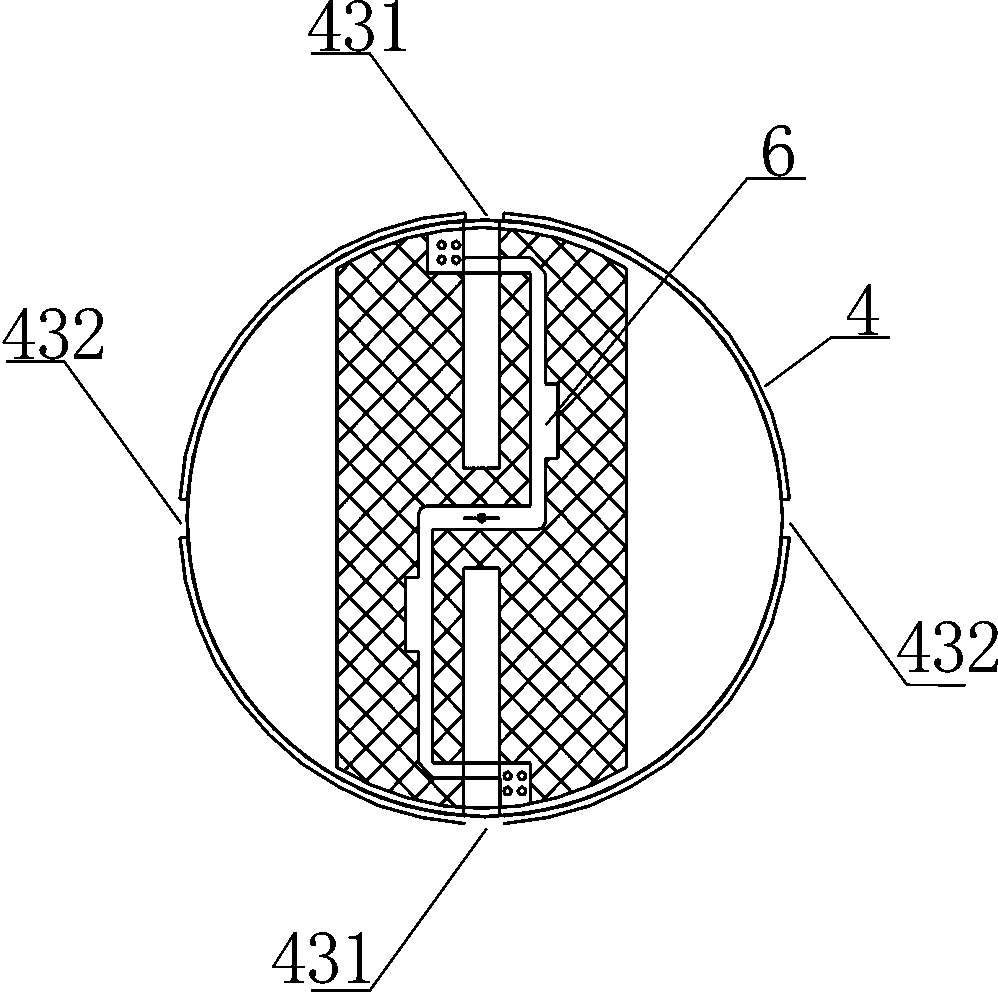
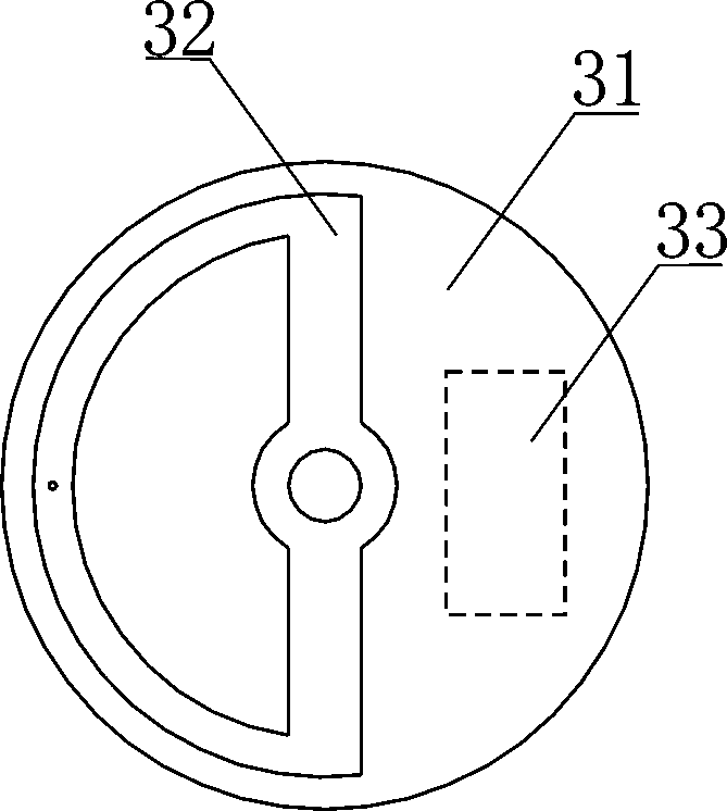
[0023] Embodiment 1: as figure 1 As shown, the integrated dual-polarized ceiling antenna includes a reflector 1, a vertically polarized feeder cable 2, a vertically polarized feeder board 3, a radiation cup 4, a horizontally polarized feeder cable 5, and a horizontally polarized feeder electric board 6, the vertically polarized feeder cable 2 is electrically connected to the vertically polarized feeder board 3, the horizontally polarized feeder cable 5 is electrically connected to the horizontally polarized feeder board 6, the reflector 1 is grounded, and the radiation The cup body 4 is composed of a cylindrical body 41 and a cone 42 arranged at the bottom of the cylindrical body. The cylindrical wall of the cylindrical body 41 is distributed with a plurality of slits parallel to the axial direction of the cylindrical body along the circumferential interval. 43 , the central axis of the radiation cup 4 is perpendicular to the reflector 1 . The horizontally polarized feeder pl...

Embodiment 2

[0027] Embodiment 2: as Figure 4 As shown, the integrated dual-polarized ceiling antenna includes a reflector 1, a vertically polarized feeder cable 2, a vertically polarized feeder board 3, a radiation cup 4, a horizontally polarized feeder cable 5, and a horizontally polarized feeder The electric board 6, the central axis of the radiation cup 4 is perpendicular to the reflector 1, and the reflector 1 is grounded. The horizontally polarized feeder plate 6 is arranged in the cylindrical body and the distance from the top of the cylindrical body is 1 / 2 of the length of the cylindrical body. The vertically polarized feeder plate 3 is set in the cone 42 of the radiation cup 4 and forms a capacitive coupling with the cone 42, and the vertically polarized feeder cable 2 penetrates from the bottom of the cone 4 of the radiation cup 4 It is electrically connected to the vertically polarized feeder board, the horizontally polarized feeder cable 5 penetrates through the side wall of ...


PUM


Abstract

The invention discloses an integrated dual-polarization ceiling antenna which comprises a reflection plate, a vertical polarization feed cable, a vertical polarization feed plate, a radiation cup, a horizontal polarization feed cable and a horizontal polarization feed plate. The reflection plate is grounded, the radiation cup is composed of a barrel-shaped body and a cone at the bottom of the barrel-shaped body, a plurality of gaps parallel to the axial direction of the barrel-shaped body are distributed on the barrel wall of the barrel-shaped body at intervals in the circumferential direction, and the horizontal polarization feed plate is arranged in the barrel-shaped body. Due to the fact that the horizontal polarization feed plate moves into the barrel-shaped body from the top of the barrel-shaped body, bandwidth is greatly increased. Due to the fact that the vertical polarization feed plate is arranged outside the cone of the radiation cup and electrically connected with the bottom of the cone, the horizontal polarization feed cable penetrates into the bottom of the radiation cup and is electrically connected with the horizontal polarization feed plate, and the barrel-shaped barrel of the radiation cup is grounded, the horizontal polarization feed cable is prevented from penetrating through the side wall of the cone of the radiation cup, and the problem that vertical polarization roundness is abnormal at part of frequency points is solved.

Description

technical field [0001] The invention relates to an antenna, in particular to a dual-polarization ceiling antenna. Background technique [0002] The existing dual-polarization ceiling antenna is mainly the Hongxin mode. The main disadvantages of the Catherine model, Comba model, and Hongxin model are the complex structure and low isolation. Although the structure of the Catherine mode is simple, but the horizontal polarization bandwidth is narrow, it cannot meet the new needs. The structure of the Jingxin mode is slightly similar to that of the Catherine mode, and the horizontal polarization is integrated with the vertical polarization. The structure is simpler than the Hongxin mode. The Catherine mode is slightly more complicated, but the horizontal polarization bandwidth has been improved, and the isolation is better than the former two. The patent document of the top antenna, this patent includes the first joint, the second joint, the metal reflector, the inner conductor...

Claims


Application Information

Patent Timeline
Patent Type & Authority Patents(China)
IPC IPC(8): H01Q21/24H01Q1/52
Inventor 丁俊涛
Owner GUANGDONG MIKWAVE COMM TECH
Learn More