Waterproof sealing structure of plastic-encapsulated stator and bearing end cover and plastic-encapsulated motor

A technology for plastically sealing stators and bearing end covers, which is applied in the direction of electrical components, electromechanical devices, and electric components, can solve problems such as poor waterproof and sealing effects, prevent easy displacement or falling off, improve assembly efficiency, and ensure stability and reliability. Effect

Active Publication Date: 2018-09-11
GUANGDONG WELLING ELECTRIC MACHINE MFG
View PDF6 Cites 0 Cited by
  • Summary
  • Abstract
  • Description
  • Claims
  • Application Information

AI Technical Summary

Problems solved by technology

[0004] The purpose of the present invention is to overcome the deficiencies of the above-mentioned prior art, and provide a waterproof sealing structure of the plastic-sealed stator and the bearing end cover and a plastic-sealed motor, which solve the technical problem of poor waterproof sealing effect between the existing plastic-sealed stator and the bearing end cover

Method used


Image

  • Waterproof sealing structure of plastic-encapsulated stator and bearing end cover and plastic-encapsulated motor
  • Waterproof sealing structure of plastic-encapsulated stator and bearing end cover and plastic-encapsulated motor
  • Waterproof sealing structure of plastic-encapsulated stator and bearing end cover and plastic-encapsulated motor

Examples


Embodiment 1

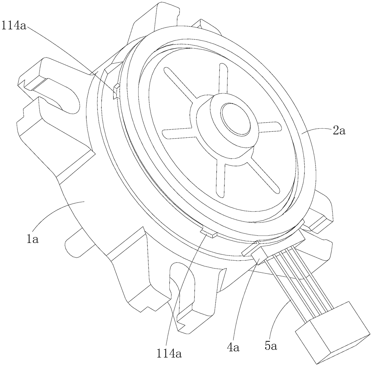
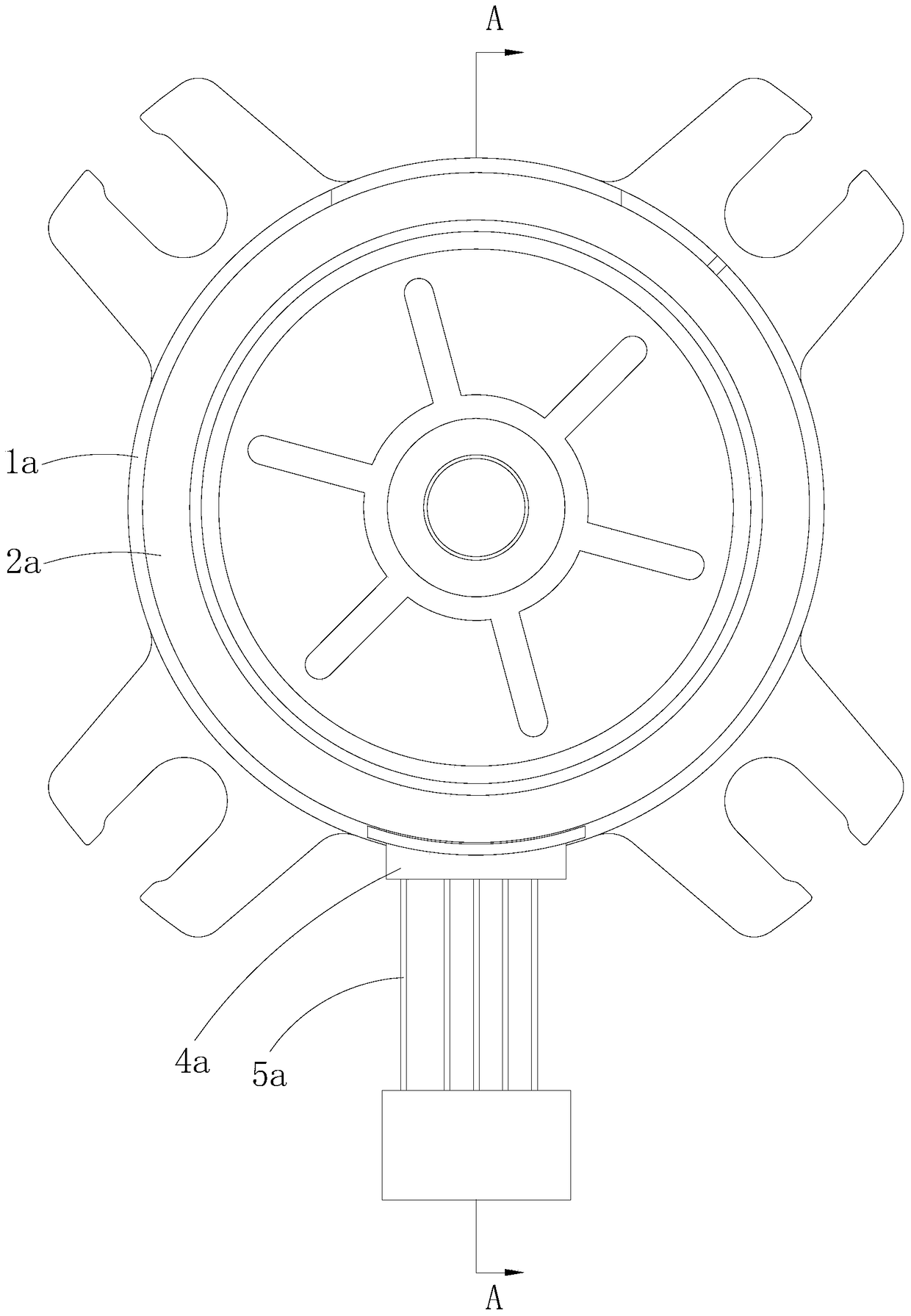
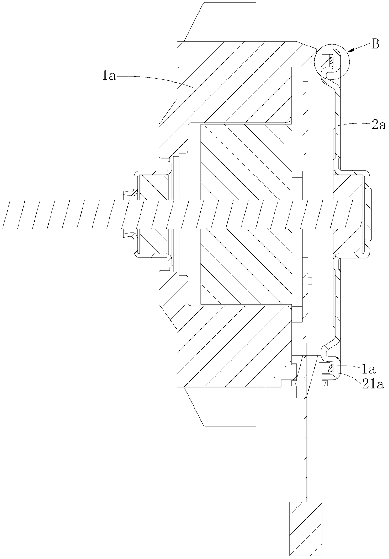
[0033] Such as Figure 1-8As shown, the waterproof sealing structure of the plastic-encapsulated stator and the bearing end cover provided by the first embodiment of the present invention includes the plastic-enclosed stator 1a and the bearing end cover 2a arranged at the outer end of the plastic-enclosed stator 1a, and the plastic-enclosed stator 1a is provided with an annular locking protrusion. edge 11a, the bearing end cover 2a is provided with an annular slot 21a that fits with the annular locking flange 11a, and the annular locking flange 11a has an axis facing the bearing end cover 2a along the axial direction of the plastic-sealed stator 1a. Towards the end face 111a, the radially inner surface 113a facing the central axis of the plastic-encapsulated stator 1a along the radial direction of the plastic-enclosed stator 1a, and the radially outer surface 112a facing away from the central axis of the plastic-enclosed stator 1a along the radial direction of the plastic-enclo...

Embodiment 2

[0042] The main difference between this embodiment and Embodiment 1 is that the shape of the top membrane part is different, specifically, as Figure 9 As shown, in the waterproof sealing structure of the plastic-sealed stator and bearing end cover and the plastic-sealed motor provided in this embodiment, the protruding sealing surface 321b is the second arc surface protrudingly provided at the middle position of the top membrane part 32b, and the two auxiliary mating surfaces 322b are two third arcuate surfaces extending smoothly along both sides of the protruding sealing surface 321b respectively. Same as Embodiment 1, the waterproof sealing membrane 3b in this embodiment includes a bottom membrane portion 31b attached to the bottom groove surface 211b and a top membrane portion 32b facing the axial end surface 111b, and the top membrane portion 32b also includes A protruding sealing surface 321b and two auxiliary mating surfaces 322b respectively located on both sides of th...

Embodiment 3

[0046] The main difference between this embodiment and Embodiment 1 and Embodiment 2 is that the shape of the top membrane part is different, specifically, as Figure 10 As shown, in the waterproof sealing structure of the plastic-sealed stator and the bearing end cover and the plastic-sealed motor provided in this embodiment, the top membrane part 32c includes two protruding sealing surfaces 321c arranged at intervals along the radial direction of the plastic-sealed stator and one The auxiliary mating surface 322c is radially located between the two protruding sealing surfaces 321c. In this embodiment, the auxiliary mating surface 322c is located at the middle position of the top membrane part 32c along the radial direction of the plastic-encapsulated stator, and the two protruding sealing surfaces 321c are respectively abutted against the inner groove surface of the annular clamping groove 21c attached to the bearing end cover 2c 213c and the outer groove surface 212c, and t...


PUM


Abstract

The invention relates to the field of motors, and discloses a plastic package stator and bearing end cap waterproof sealing structure and a plastic package motor. The plastic package stator and bearing end cap waterproof sealing structure comprises a plastic package stator and a bearing end cap at one end of the plastic package stator, wherein the plastic package stator is provided with an annular clamping flange, the bearing end cap is provided with an annular clamping groove matched with the annular clamping flange in a clamped and inserted mode, the annular clamping flange is provided with an axial end face towards the bearing end cap in the axial direction of the plastic package stator, the annular clamping groove is provided with a bottom groove face towards the plastic package stator in the axial direction of the plastic package stator, a waterproof sealing film is formed on the bottom groove face in an injection molding mode or in a coated mode, and the waterproof sealing film is elastically compressed between the axial end face and the bottom groove face The plastic package stator and bearing end cap waterproof sealing structure prevents influences of a needle insertion hole, a detection hole and a detachment notch which probably exist in the radial outer surface of the annular clamping flange on the sealing effect of a waterproof sealing ring, and achieves the aims of improving the waterproof sealing effect between the plastic package stator and the bearing end cap.

Description

technical field [0001] The invention belongs to the field of motors, in particular to a waterproof sealing structure of a plastic-sealed stator and a bearing end cover and a plastic-sealed motor with the waterproof sealing structure. Background technique [0002] Plastic-sealed motors generally have two bearing end covers located on both sides of the stator core; in traditional technology, one bearing end cover and the stator core are generally packaged in the plastic-sealed stator, and the other bearing end The cover is covered and fixed on the end of the plastic-sealed stator in an interference fit manner. For ease of description, the bearing end cover located inside the plastic-encapsulated stator is called the inner bearing end cover, and the bearing end cover located outside the plastic-enclosed stator is called the outer bearing end cover. The mating connection between the outer bearing end cover and the plastic-sealed stator is mainly realized through the cooperation...

Claims


Application Information

Patent Timeline
Patent Type & Authority Patents(China)
IPC IPC(8): H02K5/10
CPCH02K5/10
Inventor 李国雄周庆杰
Owner GUANGDONG WELLING ELECTRIC MACHINE MFG
Why Eureka
Try Eureka