Light-emitting device and control method

A light-emitting device and light-emitting device technology, which is applied in the direction of lighting devices, light sources, electric light sources, etc., can solve the problems of restricting the development of mixed light of LED lights, large power supply heat, and equipment redundancy, so as to improve equipment utilization and mix The effect of accurate light and stable load

Active Publication Date: 2017-12-29
PR LIGHTING
View PDF6 Cites 0 Cited by
  • Summary
  • Abstract
  • Description
  • Claims
  • Application Information

AI Technical Summary

Problems solved by technology

[0002] Existing LED lamps use a drive power supply and a string of LED lamp beads, all of which have the same brightness, and cannot individually control the brightness of a single lamp bead to achieve a mixed light effect
In order to achieve the effect of mixing light, so that the combination of different light color lamp beads emits different colors, it is necessary to use multiple driving power supplies to match multiple lamp beads. Each driving power supply only drives one lamp bead, resulting in redundant equipment and multiple power supplies. The heat generation is large. When there are more lamp beads that need to be dimmed, the heat generation will be greater, which restricts the development of mixed light of LED lights and causes energy waste.

Method used


Image

  • Light-emitting device and control method

Examples


Embodiment Construction

[0027] Embodiments of the present invention are described in detail below:

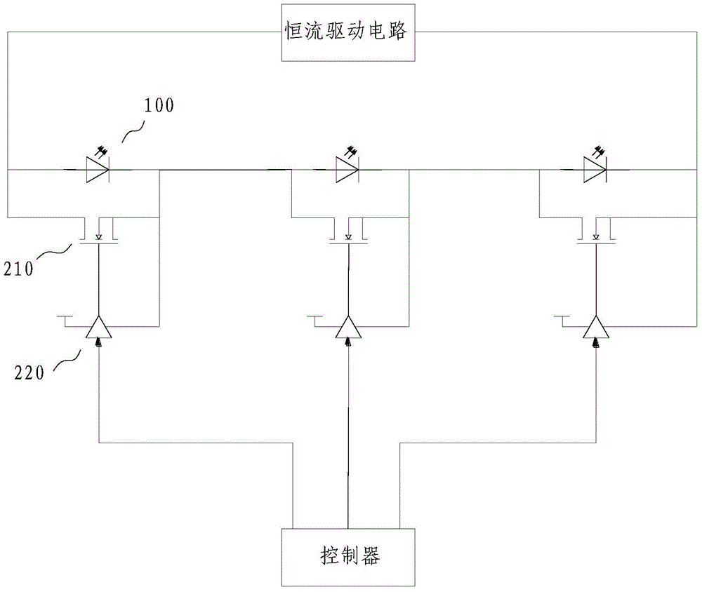
[0028] The light emitting device includes: a light emitting unit, a constant current drive circuit, and a controller.

[0029] The three light emitting units are connected in series with the constant current drive circuit.

[0030] The light emitting unit includes a light emitting branch and a bypass branch, and the light emitting branch and the bypass branch are connected in parallel.

[0031] There are light emitters on the light emitting branch, and the light emitters are light emitting diodes 100, and the light colors emitted by each light emitting diode 100 are different.

[0032] There is a switch on the bypass branch, and the switch includes a MOSFET tube 210 and a corresponding gate drive circuit 220 , the MOSFET tube 210 is electrically connected to the gate drive circuit 220 , and the gate drive circuit 220 drives the MOSFET tube 210 .

[0033] The switch has a signal input terminal, the c...


PUM


Abstract

The invention relates to a light emitting device and a control method, comprising: a light emitting unit, a constant current driving circuit, and a controller; at least two light emitting units are connected in series to the constant current driving circuit, and the light emitting unit includes a light emitting branch and a bypass branch , the light-emitting branch and the bypass branch are connected in parallel, there is a light emitter on the light-emitting branch, there is a switch on the bypass branch, the switch has a signal input terminal, the controller has a signal output terminal, and the signal input terminal is connected to the signal output terminal, The controller is used to control the on and off of the switch. Using a single constant current drive power supply to supply power to multiple light emitters has a simple structure and is easy to control. By controlling light emitters with different light colors, the light emitting devices can be precisely controlled to present different colors.

Description

technical field [0001] The invention relates to a light emitting device and a control method. Background technique [0002] Existing LED lamps use a drive power supply and a string of LED lamp beads, all of which have the same brightness, and cannot individually control the brightness of a single lamp bead to achieve a mixed light effect. In order to achieve the effect of mixing light, so that the combination of different light color lamp beads emits different colors, it is necessary to use multiple driving power supplies to match multiple lamp beads. Each driving power supply only drives one lamp bead, resulting in redundant equipment and multiple power supplies. The calorific value is large. When there are more lamp beads that need to be dimmed, the greater the calorific value, which restricts the development of mixed light of LED lamps and causes energy waste. Contents of the invention [0003] Based on this, the present invention discloses a light emitting device that...

Claims


Application Information

Patent Timeline
Patent Type & Authority Patents(China)
IPC IPC(8): H05B37/02
Inventor 韦永业
Owner PR LIGHTING
Why Eureka
Try Eureka