

Ignition circuit of separately-excited arc lighter
A technology for ignition circuits and lighters, which is applied to circuits dedicated to spark gaps, circuits, spark gaps, etc., can solve problems such as easy disconnection, shorten battery life, and affect yield, so as to reduce production costs and defective products. efficiency, avoid excessive ignition power, and facilitate mass production.
- Summary
- Abstract
- Description
- Claims
- Application Information
AI Technical Summary
Problems solved by technology
Method used
Image

Examples
Embodiment Construction
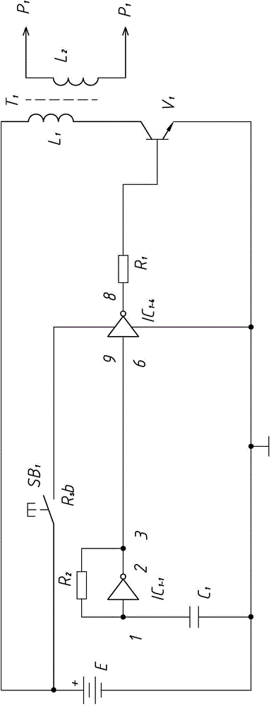
[0020] Such as figure 1 As shown, the ignition circuit of the separately excited arc lighter of the present invention includes a DC power supply E, a square wave generating circuit, a first driving and boosting circuit, and a first discharge needle P1. The first discharge needles P1 are arranged in pairs, and the first drive And the step-up circuit includes a power switch tube V1 and a high-voltage transformer T1, the winding of the high-voltage transformer T1 is composed of a low-voltage winding L1 and a high-voltage winding L2, and the power switch tube V1 is connected in series with the low-voltage winding L1 in the high-voltage transformer T1 Connected to both ends of the DC power supply E, the power switch tube V1 can be a switch transistor or a field effect tube, the first discharge pin P1 is connected to the output end of the high voltage winding L2, and the output end of the square wave generating circuit is connected to the power switch tube V1 A first drive branch is...
PUM
 Abstract
Description
Claims
Application Information