A linear motor thrust and thrust fluctuation test device and test system

A linear motor and thrust fluctuation technology, applied in measuring devices, force/torque/power measuring instruments, instruments, etc., can solve problems such as unstable connection, low safety factor, and unstable acceleration process, and achieve stable and reliable test data , high test accuracy and simple structure

Active Publication Date: 2021-06-29
GOERTEK INC
View PDF0 Cites 1 Cited by
  • Summary
  • Abstract
  • Description
  • Claims
  • Application Information

AI Technical Summary

Problems solved by technology

[0003] At present, there are some deficiencies in linear motor thrust test devices; 1) Some linear motor thrust test devices use magnetic levitation or air flotation devices to achieve the purpose of non-contact between the tested linear motor mover and stator, the device is complex, difficult to implement, and the safety factor Not high; 2) Some use servo motors and ball screws or pulleys to provide motion and thrust, the thrust is small, easy to wear, low precision, and the acceleration process is not stable, requiring the use of inertial flywheels; 3) Use screws to connect force measurement When the meter is connected to the linear motor under test, not only the connection is unstable, but also interference will be generated; when measuring the instantaneous thrust value, the data obtained is unstable and the reliability is not high; 3) At present, most linear motor thrust test devices can only be used for single To test

Method used


Image

  • A linear motor thrust and thrust fluctuation test device and test system
  • A linear motor thrust and thrust fluctuation test device and test system
  • A linear motor thrust and thrust fluctuation test device and test system

Examples


Embodiment 1

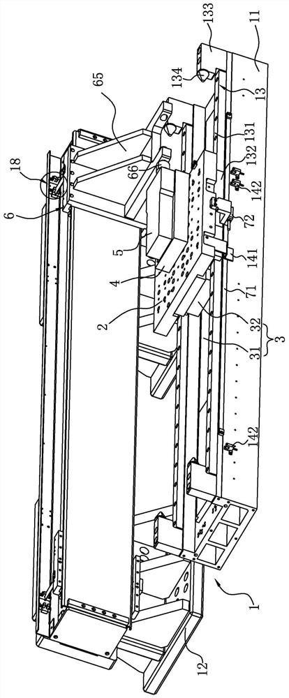
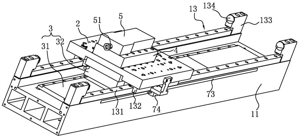
[0046] Depend on figure 1 As shown, the linear motor thrust and thrust fluctuation test device of this embodiment mainly includes a frame 1, a test platform 2, a linear motor under test 3, a dynamometer 5, a linear motion drive mechanism 6 and a displacement detection assembly.

[0047] Wherein, the frame 1 includes a base 11 in a U-shaped structure (integrated, or fixed by a horizontal plate and two vertical plates) and a bracket set spaced apart from the base 11; the linear motion drive mechanism 6 is installed in front of the bracket set. On the side, the test platform 2 is slidably installed on the top of the base 11; the bracket set includes at least two bracket monomers 12 arranged side by side along the sliding direction of the test platform 2.

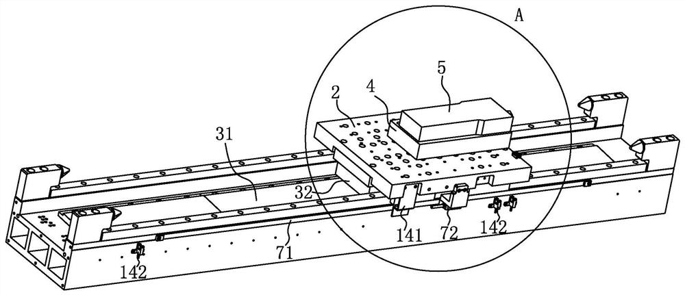
[0048] Depend on Figure 2 to Figure 4 Commonly shown, the stator 31 of the tested linear motor 3 is fixed on the bottom surface of the base 11, and the mover 32 of the tested linear motor 3 that is compatible with the stator ...

Embodiment 2

[0063] This embodiment discloses a linear motor thrust and thrust fluctuation testing system, which includes a servo driver electrically connected to the upper computer and the upper electromechanical device (the servo driver has a drive module and an encoder data processing function), and also includes the above-mentioned linear motor thrust and thrust fluctuation Test device; the double mover linear motor 61 in the linear motion drive mechanism 6, the magnetic grating reading head 72, 76 and the grating reading head 74 in the displacement detection assembly are all electrically connected to the servo driver, and the dynamometer 5 is connected to the upper computer (computer) ) electrical connections. Read the data in real time through the software installed on the host computer, and process to obtain stable and reliable thrust and thrust fluctuation values.

[0064] The following is a brief description of its working principle:

[0065]During the test, it is necessary to gr...


PUM


Abstract

The invention discloses a linear motor thrust and thrust fluctuation test device and a test system. The test device includes a frame and a test platform slidingly mounted on the frame; the stator of the linear motor to be tested is fixed on the frame, and the mover is fixed on the frame. On the test platform, there is an air gap between the stator and the mover; the dynamometer is fixed on the test platform; the linear motion drive mechanism is installed on the frame and connected with the lateral force meter; the displacement detection component is installed on the frame for Obtain the displacement of the test platform directly or indirectly. The test system includes a host computer, a servo drive connected to the host electromechanical device, a DC power supply, and a linear motor thrust and thrust fluctuation test device; the linear motion drive mechanism and displacement detection components are electrically connected to the servo drive, and the dynamometer is connected to the host electromechanical device. The linear motor is electrically connected with the DC power supply. The invention has the advantages of simple structure, high compatibility, bidirectional testing, high testing precision and stable and reliable testing data.

Description

technical field [0001] The invention belongs to the technical field of motor testing, and in particular relates to a linear motor thrust and thrust fluctuation testing device and testing system. Background technique [0002] In the field of industrial automation, high-precision and high-speed linear motors have been widely used. However, after the design and production of linear motors, a special test platform is required to evaluate their performance. The function of the test platform is to simulate the operating conditions of the motor in the machine tool to evaluate the performance of the motor by collecting performance parameters such as the output speed and thrust of the motor. Usually the manufacturer will test items such as positioning force, thrust fluctuation, thrust constant, and thrust linearity in this test. The verification of these parameters can have a comprehensive understanding of the performance of the motor. [0003] At present, there are some deficienc...

Claims


Application Information

Patent Timeline
Patent Type & Authority Patents(China)
IPC IPC(8): G01L5/12
CPCG01L5/12
Inventor 刘元江贺子和孙颖王梓铭周健豪
Owner GOERTEK INC
Why Eureka
Try Eureka