Single-tube-driven electromagnetic heating circuit

A heating circuit, electromagnetic technology, applied in induction heating, induction heating control and other directions, can solve the problems of difficult to precise control, large temperature fluctuations, circuit interference, etc., to achieve the effect of easy temperature control

Inactive Publication Date: 2017-05-31
朱佑铮
View PDF7 Cites 1 Cited by
  • Summary
  • Abstract
  • Description
  • Claims
  • Application Information

AI Technical Summary

Problems solved by technology

In the traditional single-tube drive electromagnetic heating circuit, the resonant capacitor is connected in parallel with the excitation coil and then connected in series between the positive pole of the DC current and the collector of the IGBT switch tube. During the electromagnetic heating process, the electroma

Method used


Image

  • Single-tube-driven electromagnetic heating circuit
  • Single-tube-driven electromagnetic heating circuit

Examples


Example Embodiment

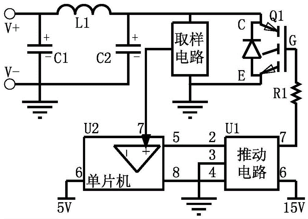
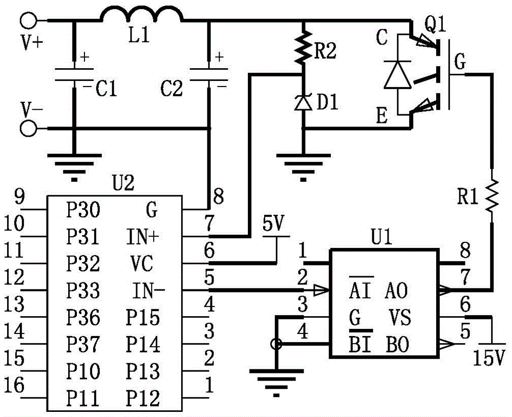
[0013] like figure 1 and 2 A single-tube drive electromagnetic heating circuit is shown, including filter capacitor C1, excitation coil L1, resonant capacitor C2, IGBT switch tube Q1 (including damping diode), sampling circuit, single-chip circuit (including voltage comparator) and driving Circuit, the filter capacitor C1 negative pole, the resonant capacitor C2 negative pole and the emitter of the IGBT switch Q1 are connected and grounded, the filter capacitor C1 positive pole is connected to the DC positive pole, and the excitation coil L1 is connected in series between the filter capacitor C1 positive pole and the resonant capacitor C2 positive pole, The positive pole of the resonant capacitor C2 is connected to the collector C of the IGBT switch tube Q1; the driving circuit U1 uses IR4426 or IR4428 chips (both contain two sets of driving circuits), and the 6 pins of the driving circuit U1 are connected to the 15V power supply, and the 3 pins and 4 pins are grounded , 7 pi...


PUM


Abstract

The invention discloses a single-tube-driven electromagnetic heating circuit in the field of electromagnetic heating. The single-tube-driven electromagnetic heating circuit comprises a filter capacitor C1, a magnet exciting coil L1, a resonance capacitor C2, an IGBT switch tube Q1, a sampling circuit, a single chip microcomputer circuit and a pushing circuit, wherein a negative electrode of the filter capacitor C1, a negative electrode of the resonance capacitor C2 and an emitting electrode E of the IGBT switch tube Q1 are connected and in ground connection; a positive electrode of the filter capacitor C1 is connected with a direct-current positive electrode, the magnet exciting coil L1 is in serial connection between a positive electrode of the filter capacitor C1 and a positive electrode of the resonance capacitor C2; the positive electrode of the resonance capacitor C2 is connected with a collector electrode C of the IGBT switch tube Q1, a grid electrode G of the IGBT switch tube Q1 is connected with the output end of the pushing circuit U1 through a current limiting resistor, the input end of the pushing circuit is connected with the output end of the single chip microcomputer U2, and the pushing circuit U1 can drive the IGBT switch tube to move. According to the single-tube-driven electromagnetic heating circuit disclosed by the invention, the resonance capacitor is in parallel connection with the collector electrode and the emitting electrode of the IGBT switch tube, so that voltage borne by the IGBT switch tube is effectively reduced when the IGBT switch tube is stopped in a work process; temperature control is easy to achieved, and the single-tube-driven electromagnetic heating circuit can be applied to varieties of electromagnetic heating equipment.

Description

technical field [0001] The invention relates to a heating circuit, in particular to an electromagnetic heating circuit. Background technique [0002] In order to improve the electrothermal conversion efficiency, electromagnetic heating is widely used in industrial production and civil fields. In the traditional single-tube drive electromagnetic heating circuit, the resonant capacitor is connected in parallel with the excitation coil and then connected in series between the positive pole of the DC current and the collector of the IGBT switch tube. During the electromagnetic heating process, the electromagnetic heating circuit usually adopts intermittent operation mode when controlling the temperature of the heating object. Due to thermal inertia, the temperature fluctuates greatly, and it is difficult to achieve precise control. Frequent start and stop of the circuit is likely to cause interference and malfunction. Contents of the invention [0003] The purpose of the pres...

Claims


Application Information

Patent Timeline
IPC IPC(8): H05B6/06
CPCH05B6/06
Inventor 朱金康康
Owner 朱佑铮
Why Eureka
Try Eureka