Busbar unit

A technology of bus bars and stators, which is applied to household components, electrical components, electromechanical devices, etc., and can solve problems such as increased conductor resistance and reduced current flowing through the main body

Active Publication Date: 2015-04-22
KYB CORP
View PDF7 Cites 5 Cited by
  • Summary
  • Abstract
  • Description
  • Claims
  • Application Information

AI Technical Summary

Problems solved by technology

If a through-hole is formed in the bus bar in this way, the cross-sectional area of ​​the main body is reduced. Therefore, when a motor or the like is driv

Method used


Image

  • Busbar unit
  • Busbar unit
  • Busbar unit

Examples


Embodiment Construction

[0015] Hereinafter, embodiments of the present invention will be described with reference to the drawings.

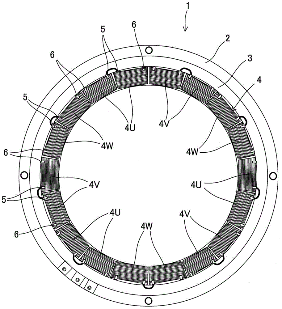
[0016] figure 1 It is a configuration diagram showing a stator 1 constituting a three-phase AC motor.

[0017] A plurality of teeth portions (not shown) are formed on the annular stator core 3 held by the case 2 so as to protrude inward. A copper wire is wound around each tooth portion, and the coil 4 is constituted by the wound wire.

[0018] Eighteen coils 4 are annularly arranged on the stator core 3 along the circumferential direction of the stator 1 . The coils 4 are composed of a U-phase coil 4U, a V-phase coil 4V, and a W-phase coil 4W, and two in-phase coils 4 are arranged at intervals of 120 degrees in the circumferential direction of the stator 1 . Therefore, three sets of one set of U-phase coils 4U, one set of V-phase coils 4V, and one set of W-phase coils 4W are sequentially arranged along the circumferential direction of the stator 1 .

[0019] In adja...


PUM


Abstract

A busbar unit formed by insert-molding a plurality of busbars, said busbars being arranged in parallel in the axial direction of a stator. Each busbar is provided with the following: a main body that extends in the circumferential direction of the stator; an insertion hole formed in said main body, wherein a supporting pin that supports the main body of another busbar during insert-molding is inserted through said insertion hole in the axial direction of the stator; and protrusions that are provided on the sides of the main body at positions corresponding to the insertion hole and increase the cross-sectional area of the main body.

Description

technical field [0001] The invention relates to a bus bar unit connected to windings of motors and generators. Background technique [0002] In Japanese JP2011-205875A, a bus bar unit is disclosed. In the bus bar unit, an insulating resin is provided between the three annular bus bars of the U-phase bus bar, the V-phase bus bar, and the W-phase bus bar. These bus bars are stacked axially along the stator. [0003] JP2011-88406A discloses that a plurality of bus bars are supported by support pins of a mold, and a bus bar unit is formed by insert molding these bus bars using an insulating resin. [0004] A through hole is formed in the main body of the bus bar constituting the bus bar unit, and a support pin that supports the main body of another bus bar during insert molding passes through the through hole. Forming the through-hole in the bus bar in this way reduces the cross-sectional area of ​​the main body. Therefore, when a motor or the like is driven, the conductor res...

Claims


Application Information

Patent Timeline
IPC IPC(8): H02K3/50
CPCH02K3/50B29C45/14065B29C2045/14147B29C45/14467B29C2045/1454B29C45/14639B29L2031/36B29L2031/749H01R25/161H02K3/28H02K3/38
Inventor 宝积宣至松前太郎黑川芳辉坂本秀泷本亨山田真吾
Owner KYB CORP
Why Eureka
Try Eureka