Current-limiting protection circuit and control method thereof

A current-limiting protection and circuit technology, which is applied to emergency protection circuit devices, overcurrent-responsive protection, circuit devices, etc., can solve the problems of inconvenient judgment and adjustment, and the current does not have a control function, so as to improve safety and Reliability, heat reduction, and current flow reduction effects

Pending Publication Date: 2020-04-24
新考思莫施电子(上海)有限公司
View PDF0 Cites 3 Cited by
  • Summary
  • Abstract
  • Description
  • Claims
  • Application Information

AI Technical Summary

Problems solved by technology

[0003] Current limiting circuits in the prior art, such as figure 1 As shown, when the current is less than the set value, the bias current of Q1 is provided by R1, and Q1 is saturated and turned on, which does not control the current; when the current is greater than or equal to the set value, the voltage drop on R increases, The sum of the voltage drop on R a

Method used


Image

  • Current-limiting protection circuit and control method thereof
  • Current-limiting protection circuit and control method thereof
  • Current-limiting protection circuit and control method thereof

Examples


Embodiment 1

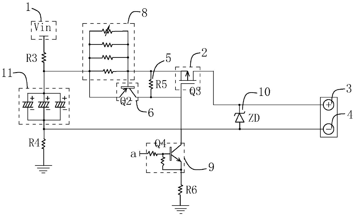
[0060] A current limiting protection circuit is arranged between the power supply terminal 1 and the equipment terminal, such as figure 2 As shown, it mainly includes the first loop and the second loop. In the first loop, the current flows to the equipment terminal through the power supply terminal 1, and the second loop is directly grounded to avoid the impact of the instantaneous large current on the equipment terminal.

[0061] In detail, one end of the first loop is electrically connected to the power supply terminal 1, and the other end is connected to the first switch element 2, the equipment-side input interface 3, and the equipment-side output interface 4 in sequence, and then grounded. The first switch part 2 is connected with a first trigger part 5 , and the first switch part 2 controls the on-off of the first circuit in response to the trigger state of the first trigger part 5 .

[0062] In this embodiment, the above-mentioned power supply terminal 1 is configured...

Embodiment 2

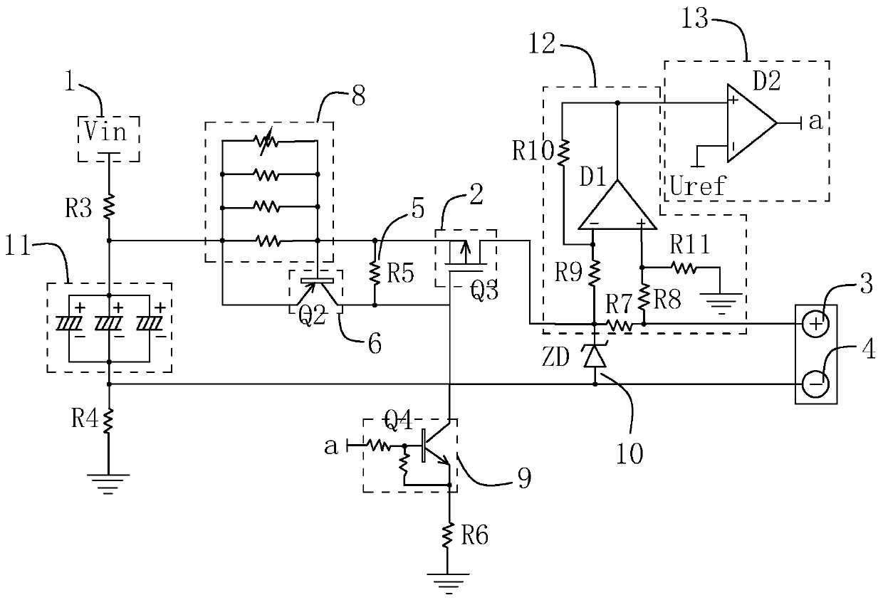
[0074] A current-limiting protection circuit, which differs from Embodiment 1 in that:

[0075] An overcurrent detection component 12 and an overcurrent determination component 13 are also configured in the current limiting protection circuit.

[0076] The overcurrent detection component 12 is configured to detect whether the current in the first loop exceeds a set value, and output a detection value signal. The detection value signal of the overcurrent judging component 13 is configured to receive the detection value signal and compare it with a reference voltage, and output the control signal.

[0077] detailed, such as image 3 As shown, the overcurrent detection component 12 includes a third resistor R7 connected in series in the first loop and a subtractor circuit connected in parallel with the third resistor R7 and set based on the first comparator D1, image 3 The middle resistor R8, the resistor R9, the resistor R10 and the resistor R11 are all set to 1KΩ, and the th...


PUM


Abstract

The invention discloses a current-limiting protection circuit and a control method thereof. The current-limiting protection circuit is arranged between a power supply end and an equipment end, and comprises a first loop comprising a first switch member and a second loop comprising a second switch member, the first loop is connected with a power supply end and the equipment end and is controlled bythe first switch member to be on and off, the second loop is connected with the power supply end and the ground and is controlled by the second switch member to be on-off, the first switch member adopts a PMOS transistor, a trigger resistor R5 connected in parallel between the source electrode and the grid electrode of the circuit provides a conduction voltage, the second switch member adopts a switching triode Q2, a resistor module is connected in series in the first loop, and after the current in the first loop rises to a preset value, the switching triode Q2 is conducted, the trigger resistor R5 is short-circuited, the first switch piece is disconnected, and the first loop is disconnected, so that the purpose of current-limiting protection is achieved; and the resistor module is arranged in a form that a plurality of first resistors are connected in parallel, and at least one of the first resistors is arranged to be an adjustable resistor, so the upper limit value of current limiting of the current-limiting protection circuit can be adjusted.

Description

technical field [0001] The present invention relates to a protection circuit, more specifically, it relates to a current limiting protection circuit and its control method. Background technique [0002] When using an external power supply to supply power to multiple devices (such as chips), if the device has a short circuit or a sudden increase in power consumption, the output of the external power supply will increase, which will affect other devices. Since each device needs to operate normally under the rated power, when the current suddenly increases, it is necessary to limit the current between the external power supply and the device. [0003] Current limiting circuits in the prior art, such as figure 1 As shown, when the current is less than the set value, the bias current of Q1 is provided by R1, and Q1 is saturated and turned on, which does not control the current; when the current is greater than or equal to the set value, the voltage drop on R increases, The sum ...

Claims


Application Information

Patent Timeline
IPC IPC(8): H02H3/08H02H3/087H02H3/093H02H3/05
CPCH02H3/006H02H3/05H02H3/08H02H3/087H02H3/093
Inventor 李元俊高山和昌
Owner 新考思莫施电子(上海)有限公司
Why Eureka
Try Eureka