Optical resonator apparatus, optical transmitter and controlling method for optical resonator

An optical resonator and equipment technology, applied in optics, optical components, nonlinear optics, etc., can solve the problems of lack of communication capability of information processing equipment and the limit of communication physical distance.

Active Publication Date: 2015-05-20
FUJITSU LTD
View PDF5 Cites 4 Cited by
  • Summary
  • Abstract
  • Description
  • Claims
  • Application Information

AI Technical Summary

Problems solved by technology

On the other hand, in communication between chips or boards, although the speed of arithmetic operation performance is increasing, communication with electrical signals reaches its limit due to the problem of physical distance
[0004] A large-scale optical communication device on a silicon substrate based on a low-loss and small-sized silicon narrow-line waveguide, i.e., silicon photonics, is expected as a technology for solving such a problem that its operation speed is increasing as described above. The lack of communication capabilities of information processing equipment

Method used


Image

  • Optical resonator apparatus, optical transmitter and controlling method for optical resonator
  • Optical resonator apparatus, optical transmitter and controlling method for optical resonator
  • Optical resonator apparatus, optical transmitter and controlling method for optical resonator

Examples


no. 1 approach

[0051] First, refer to Figure 1 to Figure 20 An optical resonator device, an optical transmitter, and a control method for the optical resonator according to the first embodiment are described.

[0052] In this embodiment mode, an optical resonator device, an optical transmitter including an optical resonator device, and a control method for an optical modulator are respectively described by taking an optical modulation device, an optical transmitter including an optical modulation device, and a control method for an optical modulator as examples. Control methods for optical resonators.

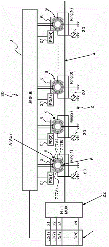
[0053] Such as figure 1 As shown in , the optical transmitter according to this embodiment includes a light source 1 , an optical multiplexing unit 22 , an optical modulation unit (optical resonance unit) 2 and a controller 3 . The optical modulation device (optical resonator device) according to the present embodiment is configured by an optical modulation unit 2 and a controller 3 . It ...

no. 2 approach

[0167] refer to Figure 21 with Figure 22 An optical resonator device, an optical transmitter, and a control method for the optical resonator according to the second embodiment are described.

[0168] In this embodiment mode, an optical resonator device, an optical transmitter including an optical resonator device, and a control method for an optical modulator are respectively described by taking an optical modulation device, an optical transmitter including an optical modulator device, and a control method for an optical modulator as examples. A control method for an optical resonator.

[0169] The optical modulation device, the optical transmitter, and the control method for the optical modulator according to the present embodiment differ from those of the first embodiment described above in the method of determining whether channel crosstalk occurs.

[0170] In particular, in the first embodiment described above, when the controller 3 controls the current amount (power ...

no. 3 approach

[0213] First, refer to Figure 23 to Figure 25 Optical resonator devices, optical transmitters, and control methods for optical resonators are described.

[0214] In this embodiment mode, the optical resonator device, the optical transmitter including the optical resonator device, and the control method for the optical modulator are respectively described by taking the optical modulation device, the optical transmitter including the optical modulator device, and the control method for the optical modulator as examples. Control methods for optical resonators.

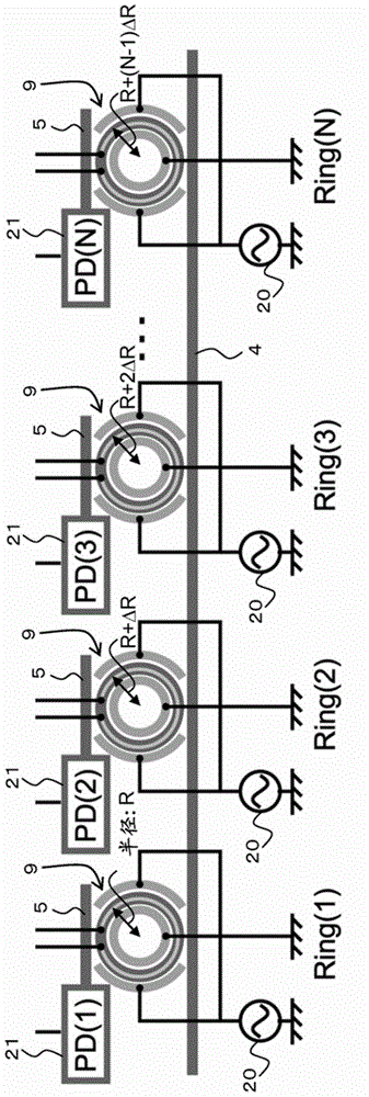
[0215] The optical resonator device, the optical transmitter, and the control method for the optical resonator according to the present embodiment differ from the first embodiment described above in the adjustment method of the resonance wavelength of the ring optical modulator 9 . In particular, in the optical resonator device, the optical transmitter, and the control method for the optical resonator in the first embod...


PUM


Abstract

An optical resonator apparatus includes an optical resonator unit wherein ring optical resonators each including a first optical waveguide and a resonance wavelength adjustment electrode are coupled in cascade connection and round-trip lengths of the ring optical waveguides are different from each other and vary in order from an input side to an output side, and a controller that adjusts a resonance wavelength of each ring optical resonator in order beginning with the ring optical resonator provided at the most input side so as to match with an input light wavelength and, when an inter-channel occurs, adjusts the resonance wavelength of the first ring optical resonator from the input side so as to match with a second-matching input light wavelength and adjusts the resonance wavelengths of the second and succeeding ring optical resonators from the input side so as to match with the first-matching input light wavelength.

Description

technical field [0001] Embodiments discussed herein relate to optical resonator devices, optical transmitters, and control methods for optical resonators. Background technique [0002] In recent years, attention has been drawn to optical functional devices on silicon substrates utilizing silicon electronic circuit fabrication techniques that can achieve large-scale integration at low cost. [0003] Furthermore, in high-performance servers, supercomputers, and the like, performance is enhanced by adopting a multi-core configuration or the like for a CPU (Central Processing Unit) so that required arithmetic operation performance can be enhanced. On the other hand, in communication between chips or boards, although the speed of arithmetic operation performance is increasing, communication with electrical signals reaches its limit due to the problem of physical distance. [0004] A large-scale optical communication device on a silicon substrate based on a low-loss and small-siz...

Claims


Application Information

Patent Timeline
Patent Type & Authority Applications(China)
IPC IPC(8): G02B6/122G02B6/43
CPCG02B6/125G02B6/43G02B6/29364G02B6/4215G02F1/0147G02F1/025G02F1/225G02F2201/16G02F2203/15G02F1/0151G02B6/28H04B10/5057H04B10/572
Inventor 早川明宪
Owner FUJITSU LTD
Why Eureka
Try Eureka