N-phase integrated buck converter

A converter and controller technology, used in output power conversion devices, instruments, and DC power input to DC power output, etc., can solve the problems of multi-phase converters, high switching losses, large time constants, etc. Achieve the effect of shortened response time, low total cost and fast switching

Inactive Publication Date: 2005-06-29
NXP BV
View PDF0 Cites 5 Cited by
  • Summary
  • Abstract
  • Description
  • Claims
  • Application Information

AI Technical Summary

Problems solved by technology

Such conventional multiphase converters suffer from a serious drawback, since the different phases cannot be superimposed on each other
In addition, the controller cannot differentiate the resulting inductor current, which leads to unstable or ineffective control
Non-superimposed phases result in slower response times for high current outputs
Therefore, conventional multiphase converters usually cannot include too many phase
[0003] Tradit...

Method used


Image

  • N-phase integrated buck converter
  • N-phase integrated buck converter
  • N-phase integrated buck converter

Examples


Embodiment Construction

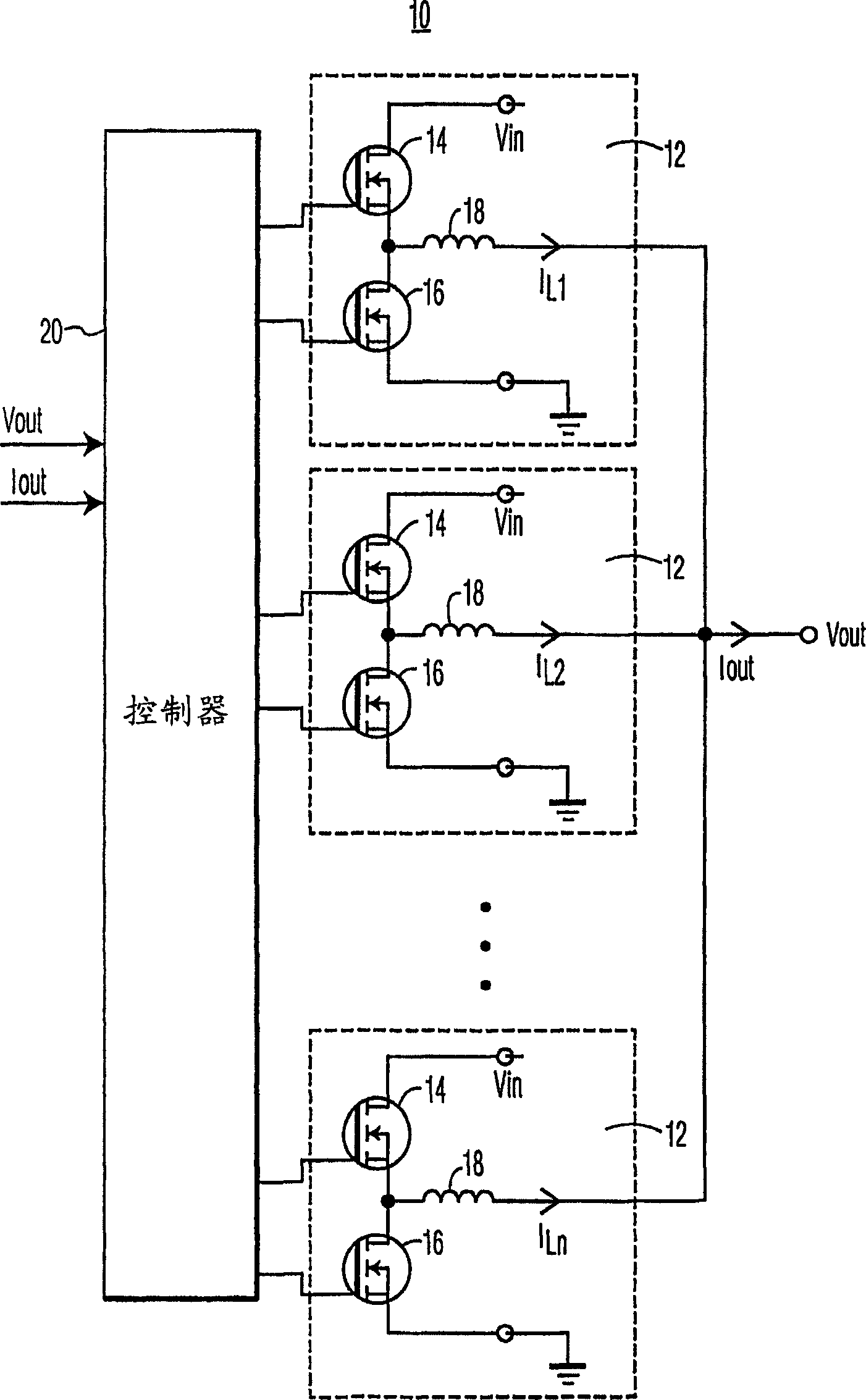
[0019] figure 1 An n-phase buck converter 10 according to an embodiment of the invention is shown. figure 1 In the example, the buck converter 10 includes a plurality (for example, n) of circuits 12 connected to an n-phase controller 20 . Each circuit 12 includes a control transistor such as MOSFET 14, a synchronous transistor such as MOSFET 16, and an inductor 18 to generate an output current IL representing one phase of the n-phase buck converter. Although MOSFETs 14 and 16 are shown as n-type MOSFETs, they could also be p-type MOSFETs.

[0020] To operate each circuit 12, the controller 20 turns on the control transistor 14 to connect the input Vin to the inductor 18 to charge the inductor. After the inductor is charged, control 20 turns off control transistor 14 to disconnect Vin from inductor 18 and turns on transistor 16 to provide a current path and discharge the inductor current to the load. As detailed below, the inductor currents originating from n circuits 12 can...


PUM


Abstract

The invention provides an n-phase integrated step-down converter (10). The converter (10) includes a controller (20) and a plurality of circuits (12), each of which is operatively connected to the controller (20). The controller controls a plurality of circuits (12) to respectively output a plurality of current signals and generate an output voltage signal, each of the plurality of current signals having an associated phase. By applying the n-phase concept of the present invention, the amount of current to be delivered per phase (ie each of the multiple circuits) is reduced. This directly reduces conduction losses per phase. Since the current per phase is lower, smaller MOSFETs can be used in each of the multiple circuits. The smaller MOSFETs are easier to switch. Therefore, the switching loss of each phase is reduced. Reducing these losses will allow the present invention to achieve high efficiency. Integration makes all components physically closer and can be switched more quickly. Higher switching frequencies allow for smaller and fewer passive components. Integration also minimizes the overall cost of the converter (10).

Description

technical field [0001] The present invention relates generally to semiconductor integrated circuit (IC) devices, and more particularly to buck converters. Background technique [0002] A buck converter is used to convert a higher voltage to a lower voltage suitable for use, for example, by a microprocessor. Buck converters typically operate using a clock whereby the inductor is charged during the first part of the clock cycle ("charge phase") and operates as a power source during the second part of the clock cycle ("discharge phase"). More recently, buck converters have evolved into multiphase buck regulators. Conventional multiphase buck converters allow multiple low currents to be sent through multiple phases, respectively. The sum of the inductor currents is provided as an output. Such conventional multiphase converters suffer from serious drawbacks, since the different phases cannot be superimposed on each other. Additionally, the controller cannot differentiate the ...

Claims


Application Information

Patent Timeline
IPC IPC(8): H02M3/155H02M3/158
CPCH02M3/1584
Inventor J·奥尔森F·J·斯鲁斯
Owner NXP BV
Why Eureka
Try Eureka