Adaptive floating combined cervical interbody cage

An intervertebral fusion, self-adaptive technology, applied in the field of intervertebral fusion, can solve the problems of large surgical incision, large surgical trauma, and inability to ensure tight fit

Inactive Publication Date: 2017-05-24
赵建华
View PDF12 Cites 0 Cited by
  • Summary
  • Abstract
  • Description
  • Claims
  • Application Information

AI Technical Summary

Problems solved by technology

In previous operations, a single intervertebral fusion cage and a single steel plate were used for fixation. The intervertebral fusion cage was not fixed with the steel plate, and there was a risk of fusion cage displacement and non-fusion, resulting in surgical failure.
There is another kind of intervertebral fusion device. The steel plate and the fusion device are fixed together for use. The steel plate is provided with fixing holes, and the fusion device is fixed through the fixing holes and screws. Although this fixing method can better limit the space of the fusion device position, but there is no relative floating space between the steel plate and the cage, and it cannot be adjusted, resulting in the inability to ensure a tight fit with the bone surface of the upper and lower adjacent cones, which seriously affects the surgical effect
In addition, after the steel plate is fixed on the fusion cage, a larger surgical incision is required when implanting, which not only causes a large surgical trauma, but also is difficult to operate, which increases the pain of the patient

Method used


Image

  • Adaptive floating combined cervical interbody cage
  • Adaptive floating combined cervical interbody cage
  • Adaptive floating combined cervical interbody cage

Examples


Embodiment 1

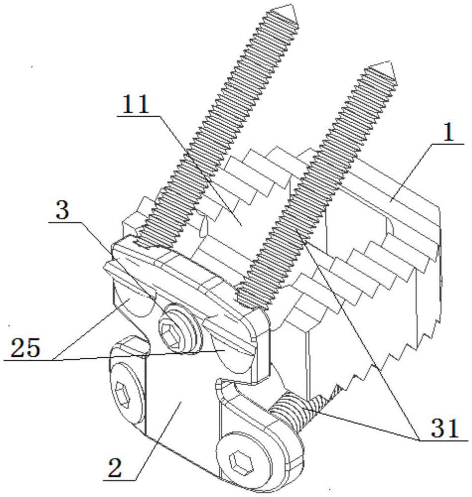
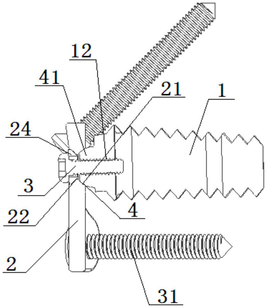
[0025] Please refer to figure 1 and figure 2 As shown, the preferred embodiment of the self-adaptive floating combination cervical intervertebral fusion device of the present invention includes: a fusion device main body 1, a steel plate 2, a screw 3 and a spherical connection mechanism 4, and the screw 3 passes through the steel plate 2 and the spherical connection The mechanism 4 is fixed on the fuser main body 1 , and the steel plate 2 is rotatably connected to the fixed end of the fuser main body 1 through the spherical connection mechanism 4 .

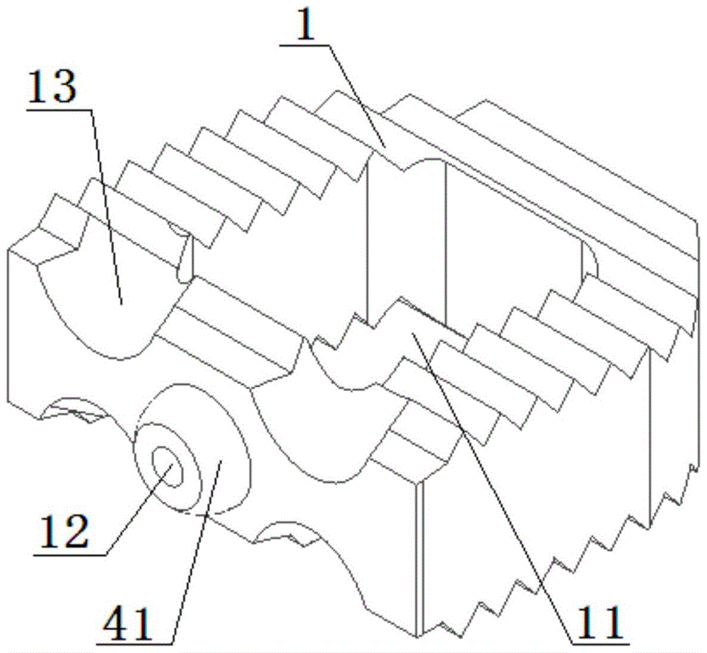
[0026] Please refer to figure 2 , image 3 , Figure 4 and Figure 5 As shown, the spherical connection mechanism 4 includes a first spherical retainer 41 arranged at the fixed end of the fusion cage body 1 and a first spherical retainer 41 arranged on the inner side of the steel plate 2 to cooperate with the first spherical retainer 41 The first spherical groove 21, the position opposite to the first spherical groove 21 on...

Embodiment 2

[0031] Please refer to Figure 7 As shown, another embodiment of the self-adaptive floating combination cervical intervertebral fusion device of the present invention includes: a fusion device main body 1, a steel plate 2, a screw 3 and a spherical connection mechanism 4, and the screw 3 passes through the steel plate 2 and the spherical connection The mechanism 4 is fixed on the fuser main body 1 , and the steel plate 2 is rotatably connected to the fixed end of the fuser main body 1 through the spherical connection mechanism 4 .

[0032] Please refer to Figure 7 , Figure 8 and Figure 9 As shown, the spherical connection mechanism 4 includes a second spherical retainer 42 disposed on the inner side of the steel plate 2 and a fixed end disposed on the fuser main body 1 to cooperate with the second spherical retainer 42 The third spherical groove 14. The outer surface of the steel plate 2 is provided with a fourth spherical groove 26 at a position opposite to the second ...


PUM


Abstract

The invention discloses an adaptive floating combined cervical interbody fusion cage comprising a cage body, a steel plate, a screw and a spherical connection mechanism. The screw penetrates the steel plate and the spherical connection mechanism to fix to the cage body, and the steel plate is rotationally connected to the fixed end of the cage body through the spherical connection mechanism. The steel plate and the cage body are connected in a floating manner, the fusion cage can be adjusted according to the implant position, the adjacent cervical surfaces are fitted tightly, the screw between the steel plate and the cage body is screwed after the adjustment to fix the steel plate and the cage body, the incision is small, and the operation difficulty is low.

Description

technical field [0001] The invention relates to an intervertebral fusion device, in particular to an adaptive floating combination cervical intervertebral fusion device. Background technique [0002] Cervical spondylotic myelopathy and cervical spondylotic radiculopathy are common and frequently-occurring diseases of middle-aged and elderly people. With the change of lifestyle, the incidence rate is also increasing year by year, and it shows a younger trend. The pathogenic mechanism of cervical spondylosis is that the cervical intervertebral disc protrudes backward after the degeneration, or the posterior edge of the pyramidal bone hyperplasia forms osteophytes that compress the spinal cord and nerve roots in the cervical spinal canal. Because the nerve cells in the spinal cord tissue are very fragile, the compression causes The loss of nerve function caused by pathological changes such as ischemia and hypoxia is irreversible. Therefore, early surgical treatment should be p...

Claims


Application Information

Patent Timeline
Patent Type & Authority Patents(China)
IPC IPC(8): A61B17/70A61F2/44
CPCA61B17/7064A61B17/7094A61B2017/7073A61F2/4425
Inventor 赵建华范伟力刘鹏
Owner 赵建华
Why Eureka
Try Eureka