Glue spraying device and glue spraying method

A technology of spraying glue and glue tank, which is applied to spraying devices, devices that apply liquid to the surface, coatings, etc., can solve the problems of complex cooling device mechanism and increase energy consumption, and achieve lower production costs, lower requirements, and avoidance of The effect of shearing

Active Publication Date: 2017-01-25
袁文兵
View PDF4 Cites 2 Cited by
  • Summary
  • Abstract
  • Description
  • Claims
  • Application Information

AI Technical Summary

Problems solved by technology

[0005] The main disadvantages of this glue spraying device are: 1. When the turntable 31 rotates at high speed, the glue with high pressure in the glue storage area 311 will rub against the inner wall of the nozzle 32 to generate a lot of heat, so a cooling device must be used to control the glue spraying device. 2. When the turntable 31 rotates at high speed, the friction between the glue with high pressure in the glue storage area 311 and the inner wall of the nozzle 32 will shear the glue, making the glue The characteristics of the glue have changed, thereby increasing the requirements for the performance of the glue

Method used


Image

  • Glue spraying device and glue spraying method
  • Glue spraying device and glue spraying method
  • Glue spraying device and glue spraying method

Examples


Embodiment Construction

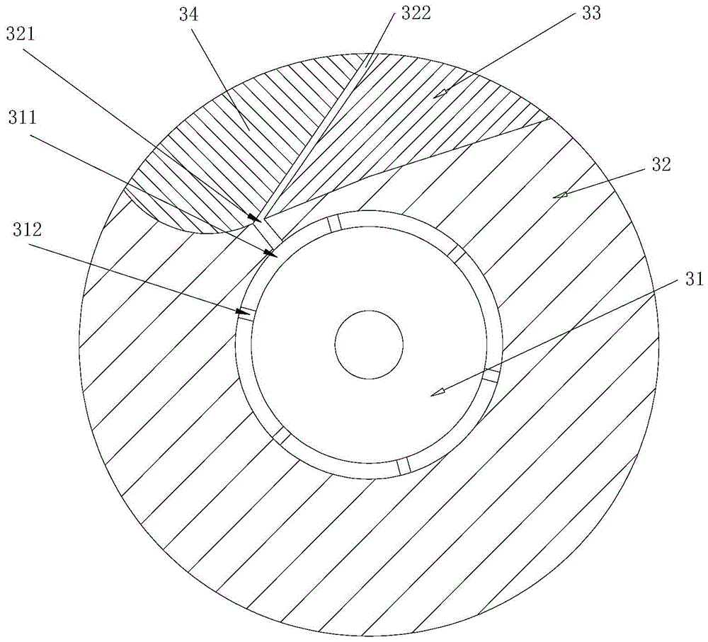
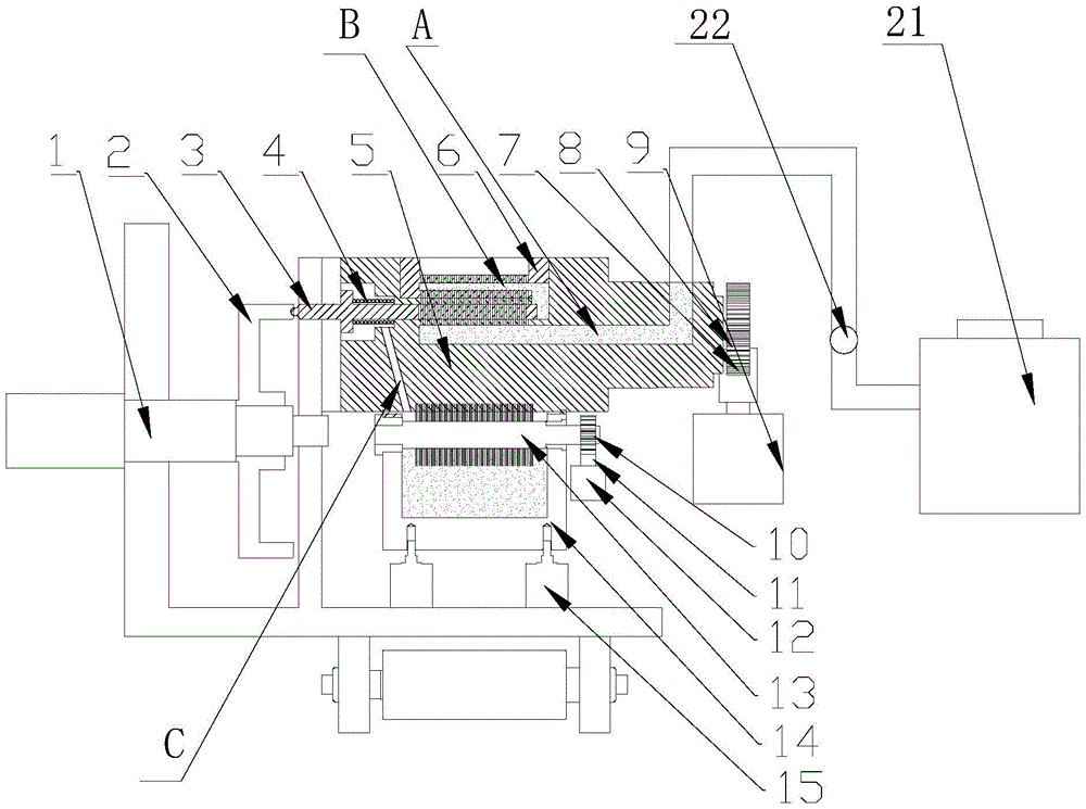
[0039] like figure 2 , image 3 As shown, the glue spraying device of the present invention includes a cam 2, the cam 2 is connected to the left end of the slide bar switch 3, and the right side of the slide bar switch 3 is connected to the compression spring 4;

[0040] The cam 2 rotates under the driving of the transmission shaft 1, and exerts a force to the right on the slide switch 3; the compression spring 4 exerts a force to the left on the slide switch 3; under the joint action of the cam 2 and the compression spring 4, Control the reciprocating linear motion of the slide bar switch 3;

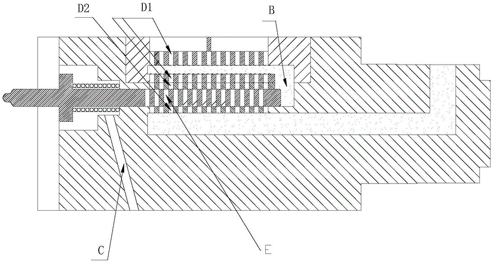
[0041] The slide bar switch 3 is movably set in the glue tank 5, and the glue tank 5 is provided with a glue storage area A, and the glue storage area A is connected to the glue box 21 through the glue delivery pipeline; the glue delivery pipeline is provided with a pump 22;

[0042] The upper part of the glue tank 5 is provided with a plurality of upper channels D1 extending longitu...


PUM


Abstract

The invention discloses a glue spraying device. The glue spraying device comprises a cam, wherein the cam is connected with the left end of a sliding rod switch; the right side of the sliding rod switch is connected with a compression spring; under the combined action of the cam and the compression spring, the reciprocating rectilinear movement of the sliding rod switch is controlled; the sliding rod switch is movably arranged in a glue cylinder; an upper channel is formed in the upper part of the glue cylinder, and a lower channel is formed in the lower part of the glue cylinder; the sliding rod switch is movably arranged between the upper channel and the lower channel; in the reciprocating rectilinear movement process of the sliding rod switch, when a connecting hole of the sliding rod switch directly faces the upper channel and the lower channel, the connecting hole connects the upper channel with the lower channel, so that glue spraying is realized; when the sliding rod switch moves for a certain distance, the connecting hole of the sliding rod switch is staggered from the upper channel and the lower channel, the upper channel is disconnected from the lower channel, and glue spraying is stopped. A complicated rotary mechanism is replaced by a simple rectilinear mechanism. Due to the fact that the rectilinear movement distance is quite small and produced heat is quite small, a cooling device does not need to be used, so that energy is saved. The invention further discloses a glue spraying method.

Description

technical field [0001] The invention relates to a glue spraying device. The invention also relates to a glue spraying method. Background technique [0002] Glue spraying systems are required in many industries, especially in the tobacco industry, where the requirements for glue spraying are very strict, and the speed and frequency of glue spraying are very high. It is difficult for general electrical devices to meet the high frequency and high precision glue spraying requirements. . [0003] For the glue spraying of the tipping paper on cigarettes, the current glue spraying is realized by a rotating mechanism. like figure 1 As shown, the existing glue spraying device includes a turntable 31, the turntable 31 is movably arranged in the center of the nozzle 32, the turntable 31 can rotate relative to the nozzle 32; An arc-shaped glue storage area 311 is formed between the two stoppers 312; the nozzle 32 is provided with a glue outlet 321, one end of the glue outlet 321 lea...

Claims


Application Information

Patent Timeline
Patent Type & Authority Patents(China)
IPC IPC(8): B05C5/00B05C11/10B05B15/02
CPCB05B15/52B05B15/55B05C5/0212B05C5/0287B05C11/1002
Inventor 袁文兵
Owner 袁文兵
Why Eureka
Try Eureka