Side flanging mechanism of stamping die

A technology of stamping die and side flanging is applied in the field of auxiliary devices of stamping die, which can solve the problems of increasing workload, unfavorable work efficiency, increasing maintenance cost, etc., and achieves the effect of improving efficiency

Inactive Publication Date: 2015-04-29
TIANJIN MOTOR DIES
View PDF0 Cites 2 Cited by
  • Summary
  • Abstract
  • Description
  • Claims
  • Application Information

AI Technical Summary

Problems solved by technology

The wedge device needs to be replaced every time the workpiece to be processed is changed, which increases the workload
At the same time, the management of multiple sets of wedge devices will also increase maintenance costs, which is not conducive to improving work efficiency

Method used


Image

  • Side flanging mechanism of stamping die
  • Side flanging mechanism of stamping die

Examples


Embodiment Construction

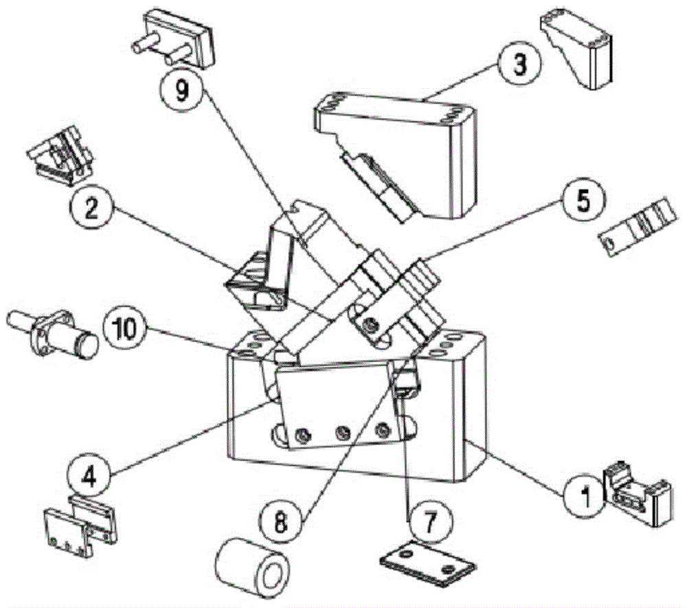
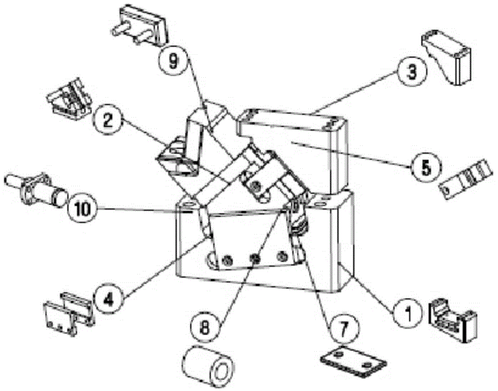
[0020] Such as figure 1 with 2 The stamping die side flanging mechanism shown includes a U-shaped slider fixing seat 1, a slider 2, an oblique pressure block 3, and a nitrogen cylinder 10;

[0021] The U-shaped sliding block fixing seat 1 is arranged on the lower mold of the mold, and is fixedly connected by bolts. The shape of the U-like slider fixing seat 1 is that the left side of the horizontal part is relatively low on the side close to the flange of the mold, and the other side is relatively high.

[0022] A slide rail 7 is provided on the upper end surface of the horizontal part of the similar U-shaped slider fixing seat 1; in this embodiment, considering the factors of processing cost and working hours, the sliding rail 7 and the U-like slider fixing seat 1 are used to process the final The way of final assembly can also be integrally processed and formed. The mode of installing after separating two pieces of processing, after long-term use, after the slide rail 7 w...


PUM


Abstract

The invention provides a side flanging mechanism of a stamping die. The side flanging mechanism is characterized in that a U-shaped slide block fixing seat is arranged on a lower die, and a slide rail is arranged on the upper end surface of the horizontal part of a slide block; a slide rail groove matched with the slide rail of the U-shaped slide block fixing seat is formed in the lower end surface of the slide block and can slide back and forth along the slide rail, the upper end surface of the slide block is an oblique surface, and a flanging insert block is arranged on the left side end surface of the slide block; the upper end surface of an oblique pressure block is fixedly connected to an upper die, the lower end surface of the oblique pressure block is an oblique surface matched with the upper end surface of the slide block and is in contact with the upper end surface of the slide block in a process of moving downwards along with the upper die, and the slide block is pushed to slide on the slide rail; a nitrogen cylinder body is fixedly connected in a mounting groove of the vertical part of the U-shaped slide block fixing seat, and a piston of the nitrogen cylinder is fixedly connected with the side surface of the slide block and can push the slide block to slide back and forth along the slide rail. The side flanging mechanism has the advantages that the efficiency is remarkably improved in comparison with a conventional singly designed flanging process, the flanging insert block can be quickly assembled to adapt to flanging of workpieces with different shapes in comparison with a tapered wedge flanging process, the commonality is good, and the processing cost of related accessories is reduced.

Description

technical field [0001] The invention belongs to the field of auxiliary devices for stamping dies, in particular to a side flanging mechanism for stamping dies. Background technique [0002] The existing stamping die flanging process generally adopts two methods: separately setting the flanging process and installing a corresponding wedge device on the stamping die. [0003] When the flanging process is set separately for large-scale and large-scale workpiece processing, there are problems such as low production efficiency and the need to separately design the flanging mold. At the same time, it also increases the work flow and reduces the efficiency of production. [0004] A corresponding wedge device is installed on the stamping die, and a matching wedge device needs to be designed and processed each time a workpiece is flanged. The wedge device needs to be replaced every time the workpiece to be processed is changed, which increases the workload. At the same time, the m...

Claims


Application Information

Patent Timeline
IPC IPC(8): B21D37/10B21D19/00
CPCB21D37/10B21D19/00
Inventor 姚鹏张海亮
Owner TIANJIN MOTOR DIES
Why Eureka
Try Eureka