Rivet installation tool having automatic riveting core guiding out mechanism

A technology for rivets and utensils, which is applied in the field of rivet installation utensils with an automatic rivet core export mechanism, and can solve problems such as impact and poor health of workers

Active Publication Date: 2015-04-29
ROBERT BOSCH GMBH
View PDF6 Cites 3 Cited by
  • Summary
  • Abstract
  • Description
  • Claims
  • Application Information

AI Technical Summary

Problems solved by technology

In addition, these monotonous and regular movements may have adverse health effects on workers

Method used


Image

  • Rivet installation tool having automatic riveting core guiding out mechanism
  • Rivet installation tool having automatic riveting core guiding out mechanism
  • Rivet installation tool having automatic riveting core guiding out mechanism

Examples


Embodiment Construction

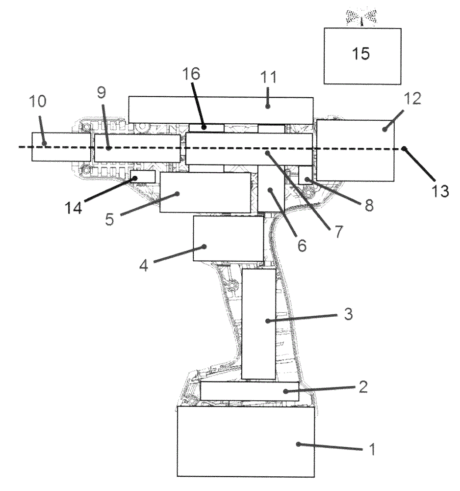
[0026] exist figure 1 The riveting tool shown in is used for installing blind rivets or blind nuts consisting of a rivet sleeve and a separable rivet mandrel. This is a battery-operated appliance for manual operation. A tool head 10 with a nozzle piece for holding the rivet mandrel is provided. Along the same axis 13, the tool head 10 and / or the force sensor with the rivet lead-through 9 and / or the trapezoidal screw or the ball screw 7 with the rivet lead-through 7 and / or preferably the rivet container are arranged next to each other 12. The rivet mandrel clamped by the nozzle part during operation can be guided through the above-mentioned components 10, 9, 7 by means of the rivet mandrel outlet channel (not shown) as far as the said rivet mandrel after its separation. Rivet mandrel container 12.

[0027] The trapezoidal screw or ball screw 7 is driven by means of the electric motor 5 , preferably in conjunction with the transmission 6 , possibly with offset. A stroke sen...


PUM


Abstract

In the prior art, the rivet core which is separated from the riveting tool is guided to the rivet core container through the appropriate movement of the rivet installation device. The invention enables the process to be automatic and gurantees the accuracy of the riveting tool and reliability of the process. As a result, the rivet installation tool having the automatic riveting core guiding out mechanism reduces the fault and reduces the circulation time of the tool.

Description

technical field [0001] The invention relates to a rivet setting tool or rivet socket or rivet attachment for industrial purposes. Background technique [0002] Rivet setting devices or systems composed thereof are known from the prior art. [0003] These systems are usually realized by means of: a higher-level controller for one or more rivet setting devices (e.g. base station, rivet controller), power components depending on the power output requirements of the rivet setting device, one or more rivet Install the appliance. The rivet setting device generally comprises at least one pulling device for pulling the rivet mandrel, the pulling device is realized by means of a drive (pneumatically, hydraulically, electrically), wherein preferably an Set up the transmission mechanism. [0004] Document EP 0 653 259 B1 discloses a method for setting blind rivets and a device in which the pulling force is generated by means of an electric motor. After installing the blind rivet, t...

Claims


Application Information

Patent Timeline
IPC IPC(8): B21J15/32B21J15/38B21J15/28
CPCB21J15/043B21J15/105B21J15/26B21J15/285B21J15/326B21J15/50
Inventor A.沙尔芬贝格D.伊韦尔
Owner ROBERT BOSCH GMBH
Why Eureka
Try Eureka