Prepressing device with protection function for processing thin-film capacitor core
A capacitor core and protective function technology, which is applied in the field of pre-pressing devices for film capacitor core processing, can solve the problems that cannot automatically drive the winding core processing process, etc., and achieve the effect of ensuring stability
- Summary
- Abstract
- Description
- Claims
- Application Information
AI Technical Summary
Problems solved by technology
Method used
Image
Examples
Embodiment 1
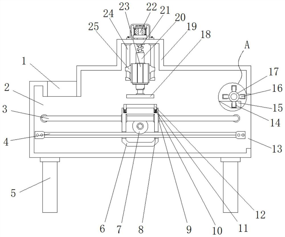
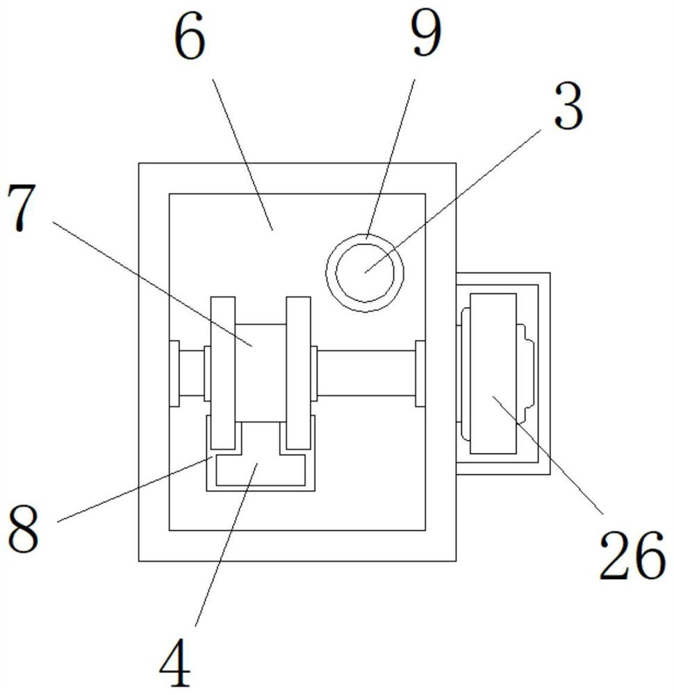
[0022] Example 1: See Figure 1-4 , a preloading device for film capacitor core processing with protection function, including a placement port 1 and a box body 2, the top side of the box body 2 is provided with a placement port 1, and the two ends on both sides of the bottom end of the box body 2 are respectively A group of pillars 5 are fixedly connected, the inside of the box body 2 is provided with a movable box 6, one side of the box body 2 is movably connected with a roller 17, one side of the box body 2 is provided with a discharge port 13, and the top of the box body 2 fixedly connected to the top box 19;
[0023] One end inside the box body 2 is fixedly connected with the limit rod 3, and the bottom of one end inside the box body 2 is fixedly connected with the slide bar 4, and a group of limit sleeves 9 are respectively provided on the top of the movable box 6 both sides, and the bottom of the movable box 6 both sides A group of through holes 8 are provided at the e...
Embodiment 2
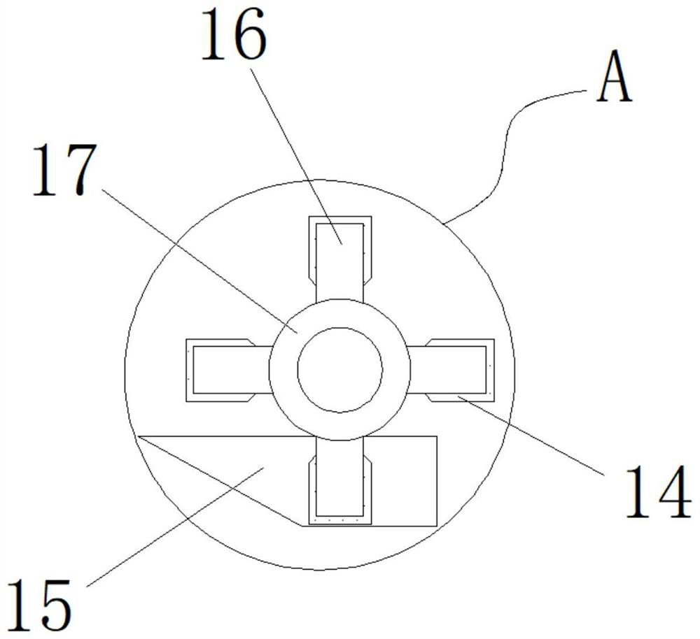
[0026] Embodiment 2: the top of the movable box 6 is provided with a groove 10, the bottom end of the groove 10 is fixedly connected with multiple groups of springs 11, and the top of the spring 11 is fixedly connected with a protective frame 12, and the same side of the two ends of the box body 2 are respectively A group of fixed inclined plates 15 are fixedly connected, and the fixed inclined plates 15 form a movable connection with the protective frame 12. There are multiple groups of pusher plates 16 fixedly connected to the outside of the rotating roller 17, and rubber sleeves 14 are fixedly connected to the outside of the pusher plate 16. One side of one end of the body 2 is fixedly connected with a stepping motor 27, and the output end of the stepping motor 27 runs through one end of the box body 2 and extends to the inside of the box body 2 to form a fixed connection with the rotating roller 17;
[0027] The centerline of the movable box 6 is on the same vertical plane ...
Embodiment 3
[0029] Embodiment 3: the top of the top box 19 is fixedly connected with a first servo motor 22, and the output end of the first servo motor 22 runs through the top of the top box 19 and extends to the inside of the top box 19. A threaded shaft 21 is fixedly connected with the threaded shaft 21 The external movable connection of threaded sleeve 20 is connected with threaded sleeve 20, and the bottom end of threaded sleeve 20 is fixedly connected with cylinder 23, and the output end of cylinder 23 is fixedly connected with pressure plate 18, and the two sides of cylinder 23 are respectively fixedly connected with a set of grooves 25, top box 19. Both sides of the inner top are respectively fixedly connected with a group of limit suspenders 24, and the limit suspenders 24 and the sleeve groove 25 form a movable connection;
[0030] The centerline of movable box 6 and the centerline of pressing plate 18 are on the same vertical plane, and the width inside top box 19 is greater tha...
PUM
 Abstract
Description
Claims
Application Information
 - R&D
- Intellectual Property
- Life Sciences
- Materials
- Tech Scout
- Unparalleled Data Quality
- Higher Quality Content
- 60% Fewer Hallucinations
Browse by: Latest US Patents, China's latest patents, Technical Efficacy Thesaurus, Application Domain, Technology Topic, Popular Technical Reports.
© 2025 PatSnap. All rights reserved.Legal|Privacy policy|Modern Slavery Act Transparency Statement|Sitemap|About US| Contact US: help@patsnap.com


