Epoxy pouring type solid insulation switch with three-cabin

A solid insulated switch, epoxy casting technology, applied in the direction of electric switches, grounding switches, switchgear, etc., can solve the problems of large volume of switches and switch cabinets, inconvenient installation, poor scalability, etc., to achieve reliable overall performance, protection The effect of strictness and simple manufacturing process

Active Publication Date: 2010-03-24
SHENYANG HAOCHENG ELECTRICAL SCI & TECH
View PDF0 Cites 12 Cited by
  • Summary
  • Abstract
  • Description
  • Claims
  • Application Information

AI Technical Summary

Problems solved by technology

[0005] The purpose of the present invention is to solve the problem that current switches and switch cabinets are too large in size, use SF6 gas to extinguish the arc and perform insulation, which will bring serious pollution to the environment, poor scalability, inconvenient installation, poor reliability, and manufacturing costs and operation and maintenance costs. The increase in electricity consumption will bring certain economic losses to the country and power users, and provide a compact structure, small size, low operation and maintenance costs, not affected by the operating environment, and can significantly reduce the investment in power facilities and transmission and feeder lines Lossy Epoxy Cast Three Compartment Solid Insulated Switches

Method used


Image

  • Epoxy pouring type solid insulation switch with three-cabin
  • Epoxy pouring type solid insulation switch with three-cabin

Examples


Embodiment

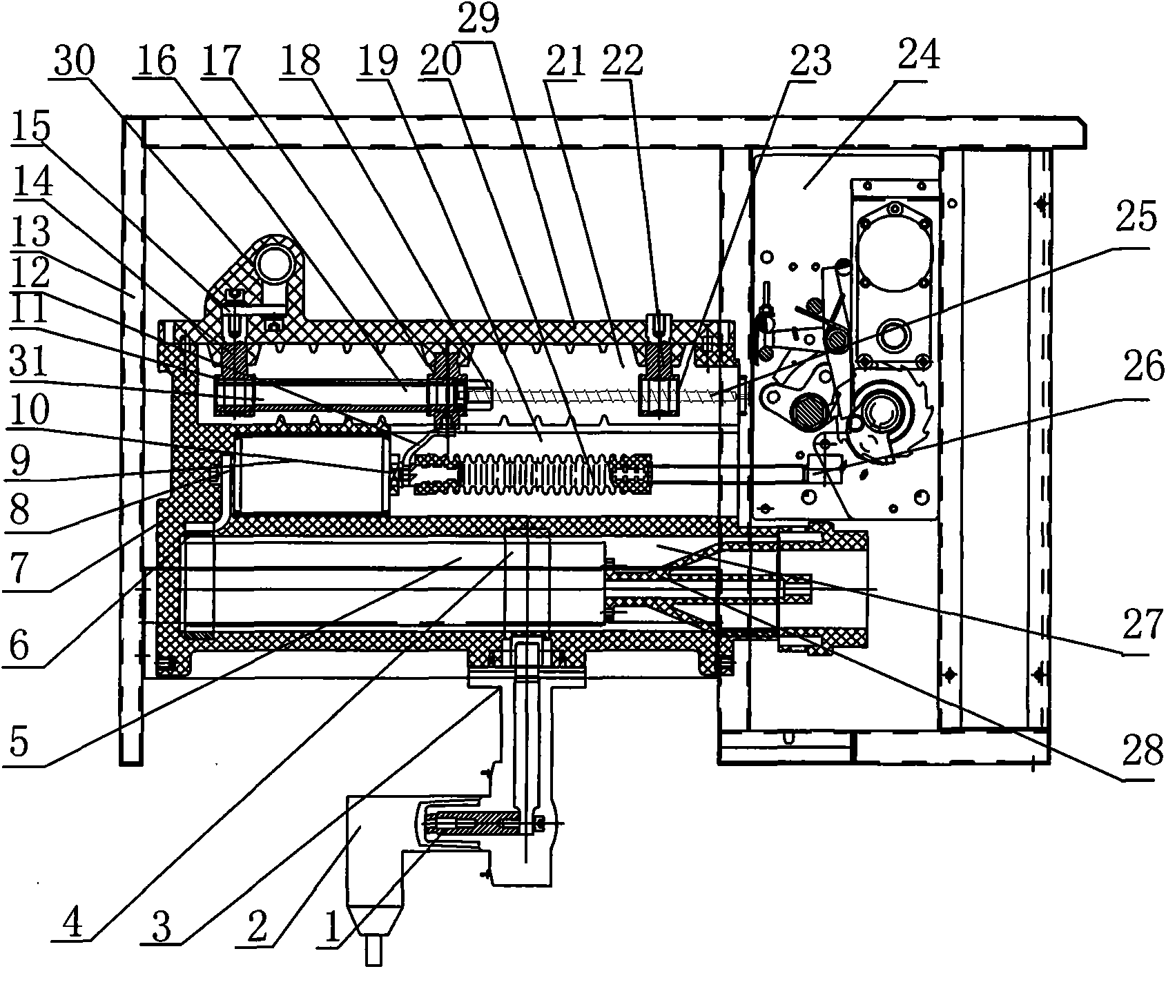
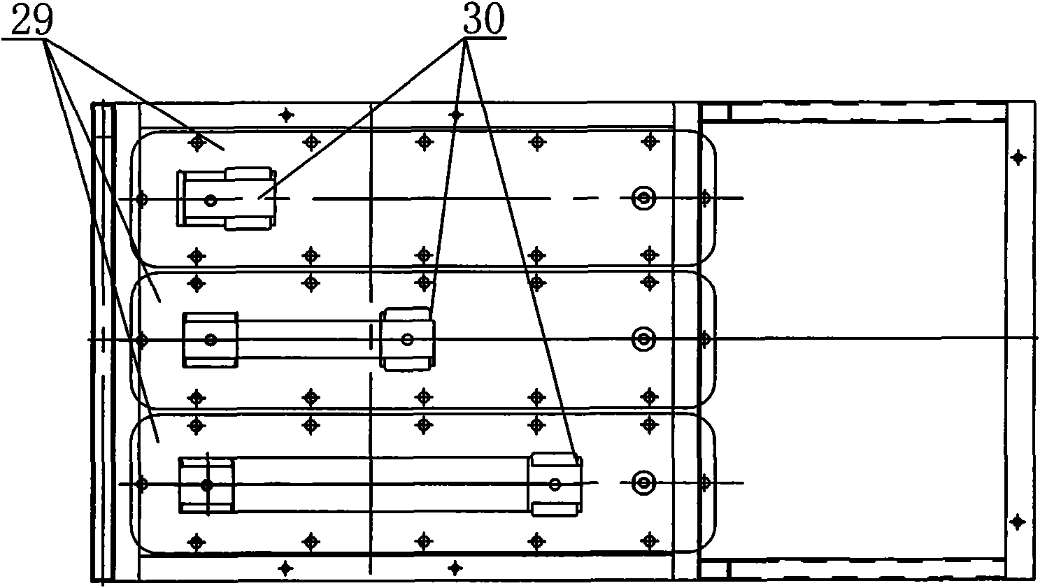
[0028] The manufacture and installation of the three-chamber epoxy cast solid insulated switch is very technical and manufacturable, and the whole switch is separated from the surrounding environment by processing the metal sheet of the shell 13 to play a role of protection and isolation. as attached figure 1 , 2 shown. The epoxy cast three-chamber solid insulated switch includes a housing 13 and three switch bodies 7 with the same structure corresponding to AC three-phase A, B and C installed in the housing 13 .

[0029] The switch body 7 includes an isolation compartment 21, a vacuum interrupter compartment 19 and a fuse compartment 27; the vacuum interrupter compartment 19 is located in the middle of the switch body 7, the isolation compartment 21 is located above the vacuum interrupter compartment 19, and the fuse compartment 27 Located below the vacuum interrupter cabin 19; the isolation cabin 21 includes an isolation switch 29, a bus contact 30, an isolation movable co...


PUM


Abstract

The present invention provides an epoxy pouring type solid insulation switch with three-cabin which is composed of three switch bodies having same structure. The switch body comprises an isolation cabin, a vacuum explosion-chamber cabin and a fuse cabin; a bus contact is arranged on the top of the isolation switch, the bus contact fixedly connects with an isolation contact through a master row; agrounding contact and the isolation contact are arranged on two ends of the isolation switch, a middle contact is in the middle; three contacts have same contact bases, sliding guide holes are arranged on the centre of the bases; the front connects with an insulation nut, the rear end connects with an operating mechanism. a through hole is arranged on the centre of the isolation moving contact andfixedly connects with the insulation nut, the insulation nut is sheathed on the nut and rotately connects with the nut; the vacuum explosion-chamber cabin and the fuse cabin are arranged below the isolation cabin respectively. The switch provided by the invention has advantages of reasonable design, higher electric safety performance, little volume, light weight, stable performance, reliable motion, stronger practicability and advancement. The switch provides assurance for reliability of electric supply, which is a precondition condition for reducing user investment.

Description

technical field [0001] The invention relates to an electric high-voltage switch, in particular to a fully insulated epoxy casting solid insulated switch with three compartments including isolation, vacuum interrupter and fuse. Background technique [0002] The power switch is one of the key equipment in the power supply industry. It is used to protect the safe operation of the generator set in the power station. It is used as a switch for the power transmission and transformation line. It is one of the key components in the relay protection and plays the role of safe power transmission. , mines, oil fields, and enterprises are used as equipment for industrial power distribution and electric traction. From this point of view, power switches play an important role in distributing electric energy and protecting power distribution equipment. [0003] The currently used power switch and the switchgear used with it are relatively large in volume, and a large amount of SF6 gas is u...

Claims


Application Information

Patent Timeline
Patent Type & Authority Applications(China)
IPC IPC(8): H02B13/00H02B1/04H02B1/20H02B1/18H01H33/04H01H31/00
CPCH01H31/003H01H33/6661
Inventor 李文东朱书明李建魏海波刘天佐
Owner SHENYANG HAOCHENG ELECTRICAL SCI & TECH
Why Eureka
Try Eureka