An agitator and a method of replacing a shaft seal of an agitator

一种搅拌器、轴封的技术,应用在化学仪器和方法、具有旋转搅拌装置的混合机、搅拌机配件等方向,能够解决增加驱动装置成本、支撑轴承受损、减速范围不能被应用等问题

Active Publication Date: 2014-10-22
SULZER MANAGEMENT AG
View PDF6 Cites 8 Cited by
  • Summary
  • Abstract
  • Description
  • Claims
  • Application Information

AI Technical Summary

Problems solved by technology

The document does not give any advice on how to support the shaft, so there is a risk that the support bearing at the second end of the shaft will be damaged as a result of the slight wobble of the shaft there
Furthermore, although it has been discussed that the plug and seal seat prevent leakage when the shaft is pulled outwards, on the one hand, it is not indicated how to keep the shaft in its pulled position during servicing of the shaft seal, and on the other hand, the shaft's Slight rocking results in a small deformation in the direction of the sealing surface, whereby there is a clear risk that the seal will start to leak
Regarding the locking of the shaft against movement in the circumferential direction by means of locking means located in the mixing vessel in communication with the liquid being mixed, it has been proven that the user can never be sure that the locking is working properly
It is very common that the fluid in the mixing vessel includes solids or some substance which tends to collect in the groove of the locking device, whereby the locking will not be secure
Finally, angular gears themselves cannot be used for the entire range of motors and mixers required for different mixing applications due to their construction being limited to a certain reduction range
Therefore, the angular gear should be combined with another reduction gear, which significantly increases the cost of the drive

Method used


Image

  • An agitator and a method of replacing a shaft seal of an agitator
  • An agitator and a method of replacing a shaft seal of an agitator
  • An agitator and a method of replacing a shaft seal of an agitator

Examples


Embodiment Construction

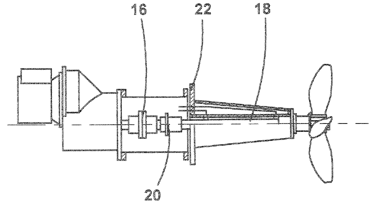
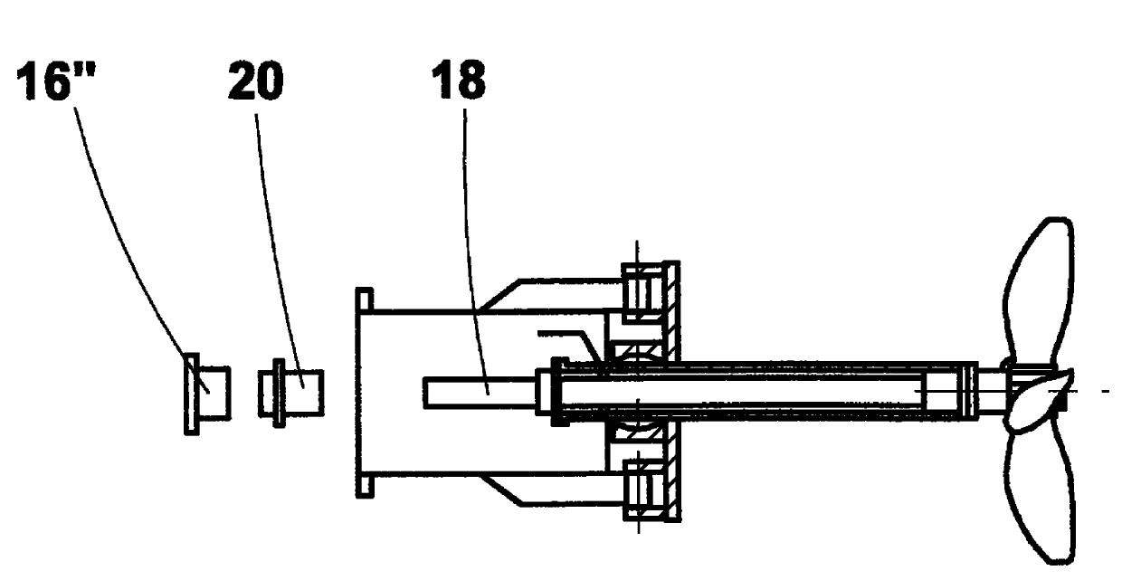
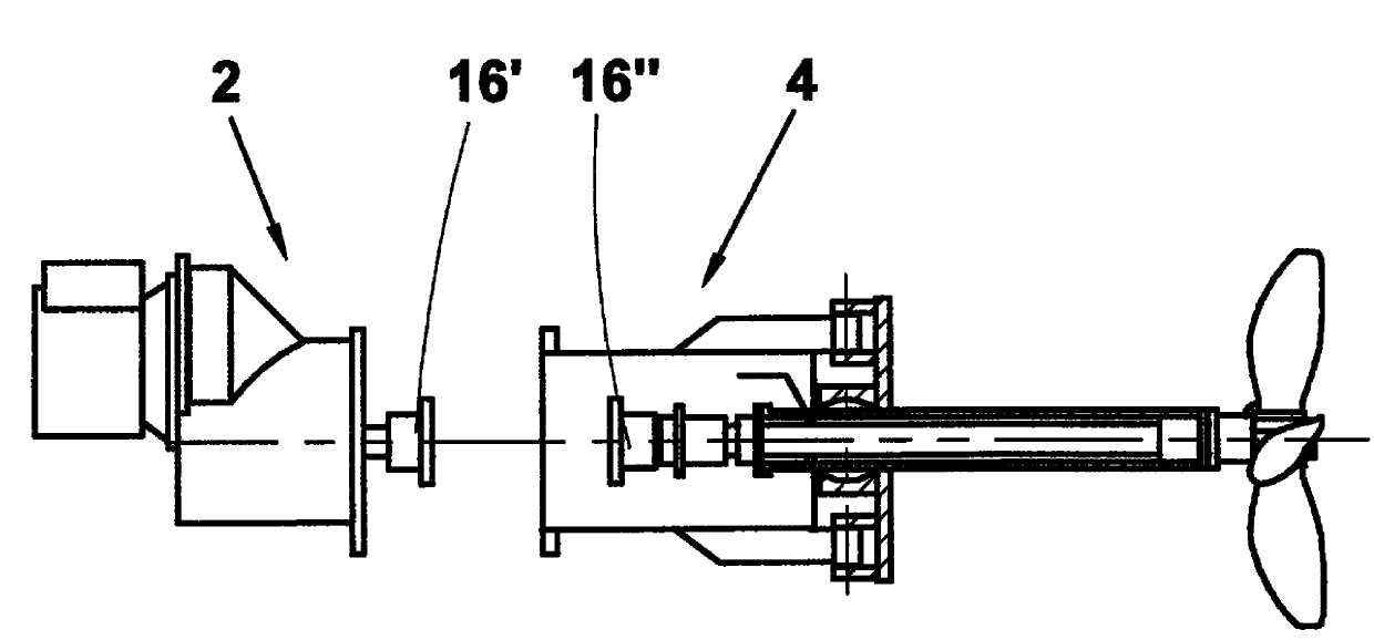
[0037] figure 1 A stirrer in its normal operating state according to a first preferred embodiment of the present invention is disclosed. The stirrer is formed by a drive unit 2 , an intermediate frame 4 , a support frame 6 and paddles 8 . The drive unit 2 comprises an electric motor 10, a reduction gear 12, a first drive shaft 14 (when a certain type of reduction gear is used) and the first half of a coupling 16 (when a certain type of coupling is used) . However, it must be understood that the coupling 16 may be any prior art coupling including, but not limited to, sleeve couplings, split sleeve couplings, and bushing couplings, whereby the coupling can All are considered to belong to the drive unit 2 or to the second drive shaft 18 . There are two basic types of reduction gears that can be used for this application. The first type shown has a first drive shaft extending from the gearbox so that the flange of a split sleeve coupling can be used. The second type has only ...


PUM


Abstract

The present invention relates to an agitator. The present invention especially relates to an agitator comprising a drive unit (2) coupled by means of a coupling (16) to a first end of a drive shaft (18), a propeller (8) attached to a second end of the drive shaft (18), the drive unit (2) being attached to a mounting flange (22) adapted for fastening the agitator to a wall of a mixing vessel, the agitator further comprising a support housing (6) having at least a tubular support frame (24) with a first end and a second end, the first end of the tubular support frame (24) being attached to the mounting flange (22), the second end of the tubular support frame (24) being provided with a support bearing (30) for supporting the second end of the drive shaft (18), wherein a shaft seal (20) is arranged at the first end of the tubular support frame (24) and sealing means (32) is arranged in connection with the second end of both the drive shaft (18) and the tubular support frame (24).

Description

technical field [0001] The present invention relates to an agitator and a method of replacing the shaft seal of an agitator. The present invention relates to a stirrer for stirring or mixing the contents of a mixing vessel, tank, tower or tank, the blades of which are located at a distance from the wall of the mixing vessel, tank, tower or tank. Preferably, the stirrer of the invention is a side-mounted stirrer, ie a stirrer fastened to the side wall of a mixing vessel, tank, column or tank. In particular, the present invention relates to such agitators and a method of replacing shaft seals of agitators without the need to empty the mixing vessel, tank, tower or tank, but within the time required for the replacement operation to be located within the mixing vessel, tank, tower or tank The paddles of the mixer inside can be left on the shaft of the mixer without the risk of leakage of the liquid to be mixed or stirred. Background technique [0002] So-called side-mounted ag...

Claims


Application Information

Patent Timeline
Patent Type & Authority Applications(China)
IPC IPC(8): B01F7/04B01F15/00B01F27/71
CPCF16J15/00B01F15/00006B01F2015/00103B01F15/00922B01F7/06B01F7/00016B01F2015/00084Y10T29/49719B01F27/051B01F27/71B01F27/60B01F33/86B01F2035/3513B01F2035/351B01F35/10B01F35/00
Inventor O.朱哈
Owner SULZER MANAGEMENT AG
Why Eureka
Try Eureka